The DR240A is an update to the DR240, adding 4 analogue inputs, and analogue output and an auxiliary 5V power output to the board in the same footprint. To add all these extra outputs, some compromises have had to be made. Specifically, the "common" signals for the optically-isolated inputs have been grouped together.
When replacing a DR240 with a DR240A, this can cause some confusion.
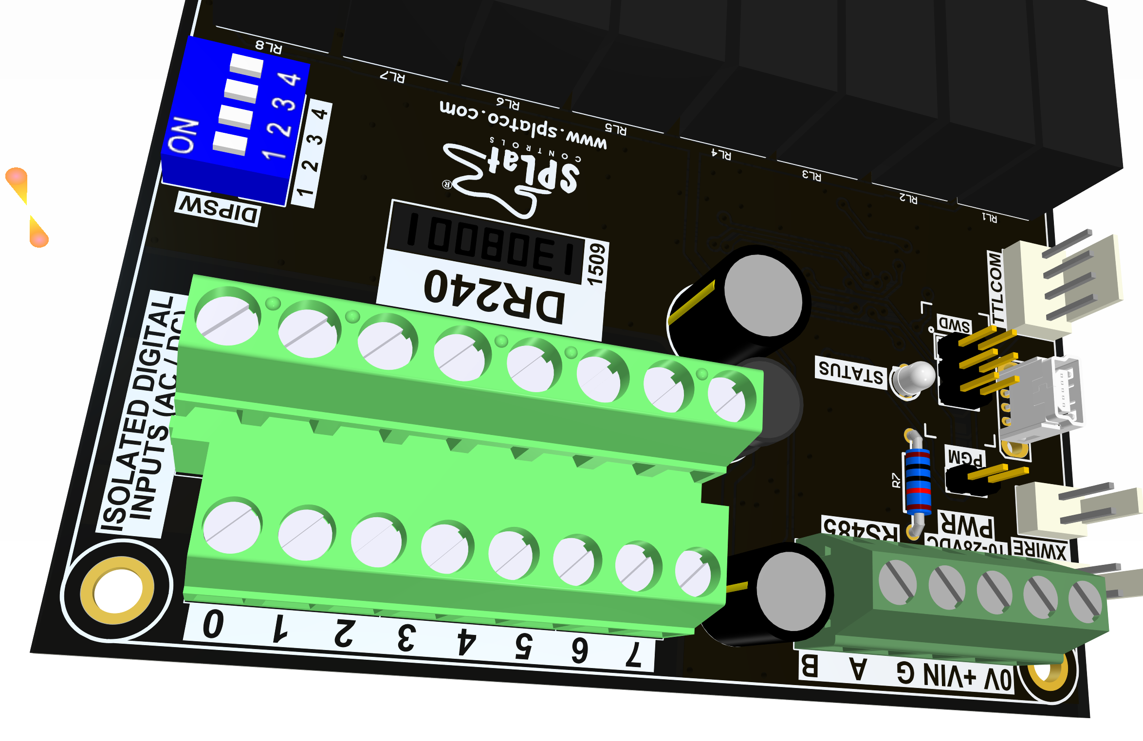
Here's the DR240 input area:
Here's the DR240A input area:
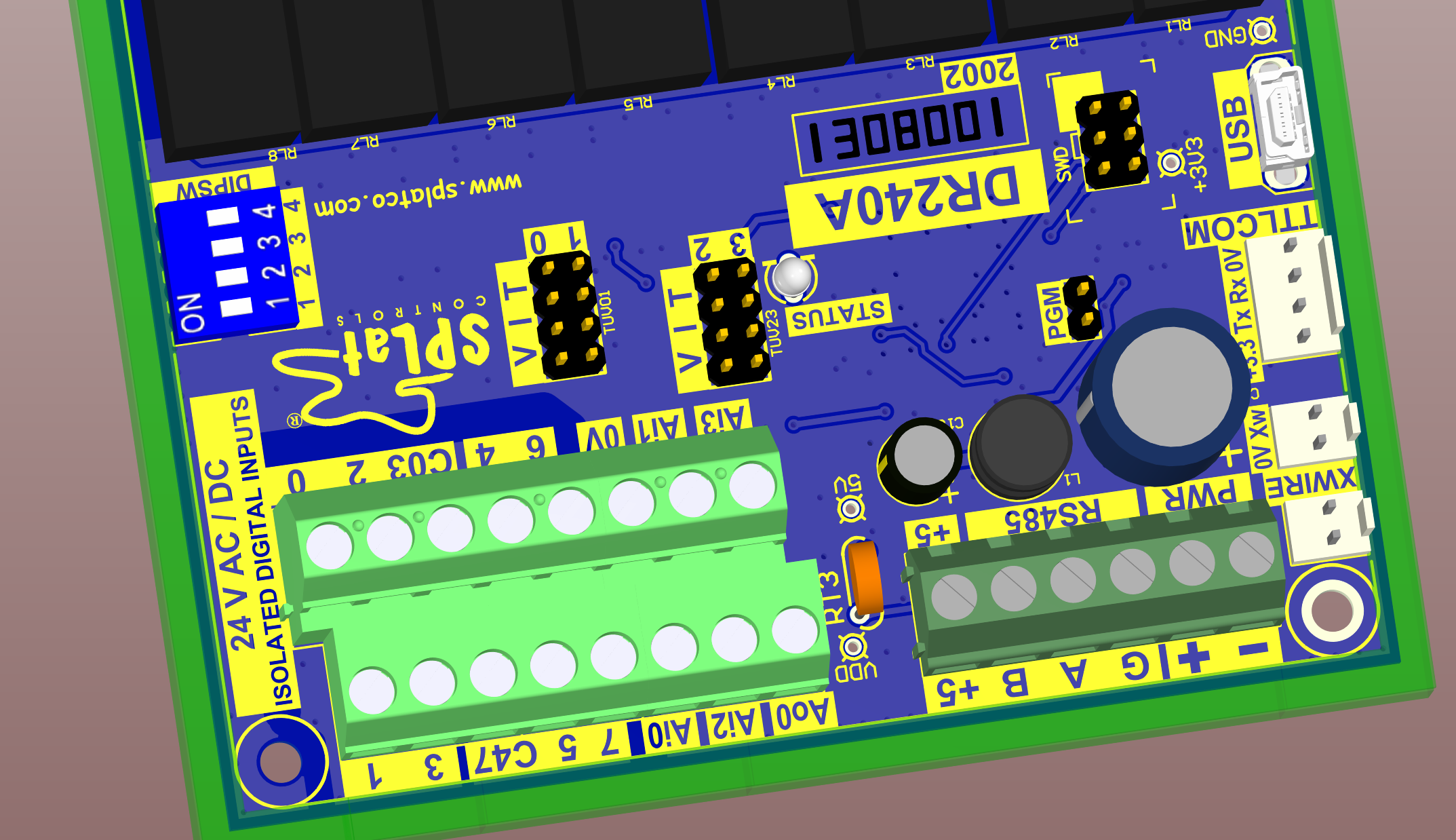
The "C03" terminal is the common signal for inputs 0 to 3, and the "C47" input is the common signal for inputs 4 to 7.
"Ao0" is the analogue output. It has a range of 0-10V and can supply up to 30mA.
"Ai0" to "Ai3" are the analogue inputs. You can use the matching "VIT" links to select the mode:
The extra "+5" pin next to the Modbus inputs is rated to supply up to 50mA.
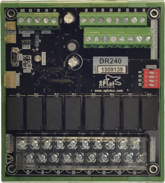
The DR240 has the following features:
The DR240A adds the following features:
It is important to note that DR240A firmware and DR240 firmware are NOT compatible with each other. However, DR240 SPlatware will work correctly on a DR240A.
The firmware download page has the tools and instructions you need for updating your DR240's firmware. The latest firmware is also available here:
The firmware download page has the tools and instructions you need for updating your DR240A's firmware. The latest firmware is also available here:
' ); EmbedProduct( 10469, '
 ' );
EmbedProduct( 10476, '
' );
EmbedProduct( 10476, '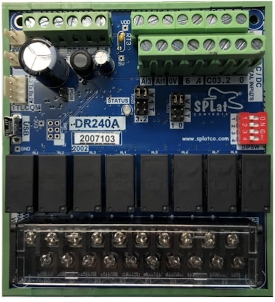 ' );
EmbedProduct( 10477, '' );
?>
' );
EmbedProduct( 10477, '' );
?>