HD8: Analog inputs
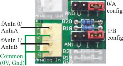
The picture above shows the connectors used for the two analog inputs, and the associated configuration jumpers.
There are two analog input channels on the HD8 board. They can be configured to operate on 0-5V, 0-10V, 0-20mA or as temperature measuring inputs (using an external thermistor sensor). In all cases the input uses one input pin and one common pin. The common pins on the analog connectors are tied to the board’s 0V terminal. Please see the article on common terminology for an explanation of the 0V terminal.
The analog inputs are designated as analog A and B in AnIn instructions or 0 and 1 in fAnIn instructions. It has a 4-pin configuration jumper field. A single jumper (shunt) on a pair of jumper pins selects the operating mode (V=voltage, I=current or T=temperature). The picture shows them both in temperature mode.
Using voltage mode
To use an analog input in voltage mode you can either
- set its jumper to bridge the two pins either side of the letter V for 0-10V range or
- remove the jumper entirely for 0-5V range,
and apply the input voltage between the input (positive) and the common (most negative). When the AnInA or AnInB instruction is executed you will get a number between 0 and 255 in the X-register (8 bit resolution). 0 represents 0 input and 255 represents full scale.
You can also use the fAnIn instruction. This will return a normalized floating point number in W which ranges from 0 at 0V in to 1.000 at full scale in. The range 0 to 1.0 is divided into 1023 steps of 0.00097752 (10-bit resolution). fAnIn selects the required channel with a numeric argument, 0 for input A, 1 for input B. The channel number in fAnIn is jndexed.
In 0-10V range the input resistance is 200KOhm. In the 0-5V range it is several mega-ohms. The accuracy is about 1.5% of full scale. There is an input noise filter comprising a single RC time constant of 5mS (0-10V) or 10mS (0-5V).
Using current mode
To use the analog input in current mode you set its jumper to bridge the two pins either side of the letter I. You then feed the current to be measured into the input pin, with the return out of the common pin. The current source (e.g. 4-20mA transmitter) must be of the type that sources a positive current from its output pin and sinks (returns) the current into its ground (or minus out) pin. Most 4-20mA transmitters are “line powered” and have a simple 2-wire connection. Connect the positive pin of the transmitter to the positive supply voltage and the negative pin to the SPLat input pin.
Some 4-20mA devices are non-loop powered. These have 3 connection wires: Positive supply, ground/negative supply and output. To connect such a device to the SPLat provide it power to its positive and ground pins, connect its ground pin to the SPLat 0V and its output to the SPLat analog input.
When the AnInA/AnInB instruction is executed, you will get a number between 0 and 255 in the X-register. 0 represents 0mA and 255 represents 20mA. At 4mA you will get a reading of 51 (plus or minus any conversion error). You can also use fAnIN, which will return 0 for 0mA, 1.0 for 20mA and 0.2 for 4mA (plus or minus any conversion error).
In current mode the input resistance is 250Ohms. The accuracy is about 1.5% of full scale. There is an input noise filter comprising a single RC time constant of 10mS.
Using thermistor mode
To use the analog input in temperature mode you set its jumper to bridge the two pins either side of the letter T and connect a suitable thermistor between the analog input pin and common. There are two basic types of thermistor: Positive Temperature Coefficient (PTC) and Negative Temperature Coefficient (NTC). The latter, NTC, is the type used for temperature measurement with SPLat. Typically, an NTC thermistor is specified as having a certain resistance at 25 degrees C.
The adjacent diagram shows the thermistor measuring circuit.
The thermistor is the bottom resistor in a voltage divider. The top resistor is a fixed onboard 10.25KOhm resistor. The voltage divider is driven by a fixed 5V source that can be switched on and off via output 4. This is an “onboard output” that is used for thermistor drive only. The purpose of switching it on and off is to minimize self-heating of the thermistor.
This arrangement differs from other models of SPLat products, where the thermistor drive voltage is programmable.
In thermistor mode the full scale analog input voltage is 5V.
A thermistor is an electronic component that changes resistance with temperature. Don’t confuse this with an RTD sensor, which also changes resistance with temperature but is much less sensitive! The warmer an NTC thermistor gets, the lower its resistance. Hence, a reading of the input voltage can be used to calculate the thermistor temperature.
You will notice that there is a 10mS time constant in the measuring circuit. This is provided to filter out hum and other noise and reduce its impact on the reading accuracy. At the same time, the 5V drive voltage is switchable via output 4, to help reduce self-heating of the thermistor. Because of the time constant, when you switch on the drive voltage it will take some time for the reading to settle down. This means your program should turn on the output, wait long enough for the reading to settle, and only then take a reading. How long should this settling time be? About 7 time constants (70mS) to settle to 0.1% (which is 10-bit resolution).
So how much error will you get from self-heating of the thermistor (assuming you don’t switch the drive)? Maximum heat dissipation (and hence self-heating) will occur when the thermistor resistance equals the drive resistance, or about 10K. The dissipation will be 0.625mW. Typically a small thermistor will self-heat by about 1°C per mW in still, free air. Hence the self heating would be about 0.6°C. In moving air, or with an enlarged surface area (say attached to a fin), or in liquid, the figure would be much less.
Accuracy and resolution depend on the thermistor you use and how you program it. The best achievable figures are about 0.1°C for both, if the system includes provision for software calibration. The SPLat Knowledge Base contains a tutorial on thermistor temperature measurement using SPLat boards. As a first approximation, when shopping for a thermistor for your application, shoot for one with a resistance of 10KOhm in the middle of the temperature range you need to cover.
How to blow up the analog input
Here are some ways of blowing up the analog inputs:
- In any mode, connect the input to a voltage greater than the positive supply or negative with respect to the 0V terminal.
- In current mode, apply more than 7.5V to the input. This will overheat the current shunt resistor and lead to loss of accuracy or, in the extreme, damage the board.