Knowledge Base
- 0.1" Connectors
- HMI700 3.3V Calibration
- HMI430/700: I/O Map (Source Code)
- HMI - Simple Example
- HMI430: Technical specification
- HMI430: EMC Report
- HMI700: EMC Report
- HMI430/700: USB Driver
- HMI430/700: File System
- HMI430/700: Power supply
- HMI430/700: OnBoard Counter type A (OBCA)
- HMI430/700: OnBoard Counter type B (OBCB)
- HMI430/700: Beeper
- HMI430/700: Crosshairs
- HMI430/700: Touchscreen calibration
- HMI430: Fitting into your product
- The CPU device
- CPU: Firmware revision
- CPU: Dialect
- CPU: Board type
- CPU: I/O configuration
- CPU: Subroutine nesting depth
- CPU: Runtime error codes
- CPU: Processor reset flags
- CPU: DTR input
- CPU: Miscellaneous resources (D>=16)
- CPU: RTS output
- CPU: Altering SuperTimer 10mS timebase [D>=20]
- CPU: Processor temperature
- MMi203: Power supply
- MMi203: Real Time Clock
- MMi203: OnBoard Counter type A (OBCA)
- MMi203: OnBoard Counter type B (OBCB)
- MMi203: OnBoard Quadrature Counter (OBQC)
- MMi202: CPU device
- MMi203: CPU device
- MMi99: CPU Device
- MMi203: Option links
- MMi203: SPice connector
- MMi203: Xwire
- MMi202: Comms connector
- MMi203: Comms connector
- MMi203: Communications
- MMi203: MultiTrack
- MMi203: Operating temperature ratings
- CC16 product documentation
- DR8 product documentation
- DW2 Product Documentation
- MMi99 Product documentation
- MMi200 product documentation
- MMi201 Product documentation
- MMi202 Product documentation
- SL99 product documentation
- The CPU device
- CPU: Firmware revision
- CPU: Dialect
- CPU: Board type
- CPU: I/O configuration
- CPU: Subroutine nesting depth
- CPU: Runtime error codes
- CPU: Processor reset flags
- CPU: DTR input
- CPU: Miscellaneous resources (D>=16)
- CPU: RTS output
- CPU: Altering SuperTimer 10mS timebase [D>=20]
- CPU: Processor temperature
- CPU: Unique ID
- 32bit Controller Enhancements
- iiChrPrintX dest# [D>=23]
- DecI
- DecM mm+
- DecX
- DecMGoIfNZ mm*+,LLLL
- DecMRetIfNZ mm+
- DecMRetIfZ mm+
- DMGNZ mm*+,LLLL
- fDec
- fInc
- iifPrintWVW dest#,f,p [D>=23]
- iifPrintWFW dest#,f,p [D>=23]
- GetCount7 [D= 4 to 15]
- iiHexPrintX dest# [D>=23]
- IncI
- IncM mm+
- IncX
- OBCA_fRead
- OBCA_GoIfNoRdg line
- OBCA_GoIfRdg line
- OBCA_Mode m
- OBCA_RetIfNoRdg
- OBCA_WaitRdg
- OBCB_GoIfA LLLL
- OBCB_GoIfB LLLL [D>=19]
- OBCB_fRdClr c+ [D>=19]
- OBCB_fRead c+ [D>=19]
- OBCB_Start c+ [D>=19]
- OBCB_StartA c [D>=19]
- OBCB_Stop c+ [D>=19]
- OBCB_StopB c+ [D>=19]
- OBQC_Clr c [D>=16]
- OBQC_fGet c [D>=16]
- OBQC_fSet c [D>=16]
- OBQC_Status c [D>=17]
- iiPrintFill dest#,count,value [D>=23]
- iisPrintXFW dest# [D>=23]
- iisPrintXVW dest# [D>=23]
- iiuPrintXFW dest# [D>=23]
- iiuPrintXVW dest# [D>=23]
- SetCount7 [D= 4 to 15] DEPRECATED
- ModBus: Resource mapping
- ComDevAddr [D>=17]
- aComDevAddr pp [D>=29]
- ComHaltScript [D>=17]
- ComResumeScript [D>=17]
- ComRunScript pppp [D>=17]
- MODBUS Number Format
- ReadCoil(s) - 1, SlaveAddr, CoilAddr16, ItemCount, SPAddr16
- ReadInputs - 2, SlaveAddr, InAddr16, ItemCount, SPAddr16
- ReadHregs - 3, SlaveAddr, RegAddr16, ItemCount, SPAddr16, NumFormat
- ReadInRegs - 4, SlaveAddr, InRegAddr16, ItemCount, SPAddr16,NumFormat
- ForceCoil - 5, SlaveAddr, CoilAddr16, SPAddr16
- PresetHreg - 6, SlaveAddr, RegAddr16, SPAddr16, SPMode
- ForceMultCoils - 15, SlaveAddr, CoilAddr16, ItemCount, SPAddr16
- PresetMultRegs - 16, SlaveAddr, RegAddr16, ItemCount, SPAddr16, SPMode
- GoTo - 128, NVPtr16
- Stop - 129
- Delay - 130, Time
- Com_Flags [D>=23]
- ComRx_BufLen [D>=23]
- ComRx_DelXChars [D>=23]
- ComRx_FindXInBuf (X) [D>=23]
- ComRx_fGetNum fw [D>=26]
- ComRx_GetHex [D>=23]
- ComRx_Peek (X) [D>=23]
- ComRx_ReadOne [D>=23]
- ComTx_Space [D>=23]
- ComRx_StrFind c [D>=27]
- ComRx_StrFind2 c [D>=29]
- ComRx_Trim (X) [D>=23]
- ComTestStartTimer [D>=17]
- ComSetCCB pppp [D>=17]
- aCom_Flags pp [D>=29]
- aComRx_BufLen pp [D>=29]
- aComRx_DelXChars pp [D>=29]
- aComRx_FindXInBuf (X) [D>=23]
- aComRx_fGetNum pp,fw [D>=29]
- aComRx_GetHex pp [D>=29]
- aComRx_Peek pp [D>=29]
- aComRx_ReadOne pp [D>=29]
- aComRx_StrFind pp,c [D>=28]
- aComRx_StrFind2 pp,c [D>=29]
- aComRx_Trim pp [D>=29]
- aComTx_Space pp [D>=29]
- aComSetCCB pp,nnnn [D>=29]
- iFindXInBuf bb*,nn [D>=28]
- iiChrPrintX dest# [D>=23]
- iifGetNum bb#,nn,fw [D>=28]
- iifPrintWFW dest#,f,p [D>=23]
- iifPrintWVW dest#,f,p [D>=23]
- iiGetHex bb#,nn [D>=28]
- iiHexPrintX dest# [D>=23]
- iiPrintFill dest#,count,value [D>=23]
- iiPrintNVText dest# [D>=27]
- iiPrintText dest#,text-string [D >= 23]
- iisPrintXFW dest# [D>=23]
- iiStrFind bb#,nn,c [D>=28]
- iiStrFind2 bb#,nn,c [D>=29]
- iiuPrintXFW dest# [D>=23]
- iiuPrintXVW dest# [D>=23]
- iisPrintXVW dest# [D>=23]
- aComRx_fGetNum pp,fw [D>=29]
- ComRx_fGetNum fw [D>=26]
- fAbs
- fAdd
- fAnIn c+ [D>=18]
- fAnOut c+ [D>=18]
- fCompareR
- fDec
- fDiv
- fGetTimer t
- fGoIfNeg LLLL
- fGoIfNZ LLLL
- fGoIfPos LLLL
- fGoIfWGEQ LLLL [D>=23]
- fGoIfWGTQ LLLL [D>=23]
- fGoIfWLEQ LLLL [D>=23]
- fGoIfWLTQ LLLL [D>=23]
- fGoIfZ LLLL
- fIEEEtoWR [D>=21]
- fInc
- fix
- FixToMem16S mm* [D>=21]
- FixToMem16U mm+ [D>=21]
- fLoadQ ffff
- fLoadW ffff
- float
- FloatMem16S mm* [D>=21]
- FloatMem16U mm+ [D>=21]
- fMul
- fNeg
- fPulse0 [D>=19]
- fRecallQ mm*+
- fRecallW mm*+
- fSetTimer t
- fSign
- fStore mm*+
- fSTSinceMark [D>=22]
- fSTTimeSince aa+ [D>=16]
- fSub
- fSwap
- fTest
- fTestWeqQ [D>=24]
- fTestWeqZ [D>=25]
- fTestWgeQ [D>=25]
- fTestWgeZ [D>=25]
- fTestWgtQ [D>=25]
- fTestWleQ [D>=25]
- fTestWltQ [D>=25]
- fTestWltZ [D>=25]
- fTestWneQ [D>=25]
- fTestWneZ [D>=25]
- fWtoQ
- fWtoIEEER [D>=21]
- iifGetNum bb#,nn,fw [D>=28]
- iifPrintWFW dest#,f,p [D>=23]
- iifPrintWVW dest#,f,p [D>=23]
- NVfGetEndW [D>=15]
- NVfGetPtrW [D>=15]
- NVfGetRecNumW [D>=15]
- NVfPutPtrW [D>=15]
- NVfPutRecNumW [D>=15]
- NVfReadQ nn*+ [D>=15]
- NVfReadW nn*+ [D>=15]
- NVfWriteW nn*+ [D>=15]
- OBCA_fRead
- Result codes for fAdd, fSub, fMul, fDiv
- Result codes for fCompareR
- Result codes for fInc, fDec
- Result codes for fix
- Result codes for fSetTimer
- Result codes for fTest
- Branch
- BranchJ [D>=16]
- BranchM mm+
- BranchR
- DecMGoIfNZ mm*+,LLLL
- DecMRetIfNZ mm+
- DecMRetIfZ mm+
- fGoIfNeg LLLL
- fGoIfNZ LLLL
- fGoIfPos LLLL
- fGoIfWGEQ LLLL [D>=23]
- fGoIfWGTQ LLLL [D>=23]
- fGoIfWLEQ LLLL [D>=23]
- fGoIfWLTQ LLLL [D>=23]
- fGoIfZ LLLL
- GoIfF LLLL
- GoIfInK ii+,LLLL
- GoIfInOff ii+,LLLL
- GoIfInOn ii+,LLLL
- GoIfINZ LLLL
- GoIfIZ LLLL
- GoIfMEQ mm+,nn,LLLL
- GoIfMGE mm+,nn,LLLL
- GoIfMGT mm+,nn,LLLL
- GoIfMLE mm+,nn,LLLL
- GoIfMLT mm+,nn,LLLL
- GoIfMNE mm+,nn,LLLL
- GoIfMNZ mm+,LLLL
- GoIfMZ mm+,LLLL
- GoIfNZ LLLL
- GoIfRTCEvent e+,LLLL [D>=16]
- GoIfSF ss,bb+,LLLL [D>=12]
- GoIfSim LLLL
- GoIfST ss,bb+,LLLL [D>=12]
- GoIfT LLLL
- GoIfUF n,m,line
- GoIfUT n,m,line
- GoIfXEQ nn,LLLL
- GoIfXGE nn,LLLL
- GoIfXGT nn,LLLL
- GoIfXLE nn,LLLL
- GoIfXLT nn,LLLL
- GoIfXNE nn,LLLL
- GoIfZ LLLL
- GoSub LLLL
- GoSubIfF LLLL
- GoSubIfMNZ mm+,LLLL
- GoSubIfMZ mm+,LLLL
- GoSubIfNZ LLLL
- GoSubIfST ss,bb+,LLLL [D>=12]
- GoSubIfT LLLL
- GoSubIfXEQ nn,LLLL
- GoSubIfXGE nn,LLLL
- GoSubIfXGT nn,LLLL
- GoSubIfXLE nn,LLLL
- GoSubIfXLT nn,LLLL
- GoSubIfXNE nn,LLLL
- GoSubIfZ LLLL
- GoTo LLLL
- OBCA_GoIfNoRdg line
- OBCA_GoIfRdg line
- OBCA_GoSubIfRdg line
- OBLCD_GoIfBusy line
- OBLCD_GoIfIdle line
- RetIfF
- RetIfMNZ mm+
- RetIfMZ mm+
- RetIfNZ
- RetIfT
- RetIfZ
- Return
- Suspend mm*+ [D>=12/15]
- Target LLLL
- #IF, #ELSEIF, #ELSE, #ENDIF (Conditional code translation)
- ClrS ss+,bb* [D>=12]
- DecI
- fRecallQ mm*+
- fRecallW mm*+
- fStore mm*+
- GoIfINZ LLLL
- GoIfIZ LLLL
- iiChrPrintX dest# [D>=23]
- iifPrintWFW dest#,f,p [D>=23]
- iifPrintWVW dest#,f,p [D>=23]
- iiHexPrintX dest# [D>=23]
- iiPrintFill dest#,count,value [D>=23]
- iiPrintNVText dest# [D>=27]
- iiPrintText dest#,text-string [D >= 23]
- iisPrintXFW dest# [D>=23]
- iisPrintXVW dest# [D>=23]
- iiuPrintXFW dest# [D>=23]
- iiuPrintXVW dest# [D>=23]
- IncI
- Input ii*+
- InputF ii*+
- InputK ii*+
- InputO ii*+
- ItoX
- LoadI nn
- Off oo*+
- On oo*+
- Output oo*+
- NotS ss+,bb* [D>=12]
- NVfReadQ nn*+ [D>=15]
- NVfReadW nn*+ [D>=15]
- NVfWriteW nn*+ [D>=15]
- NVPopByte nn*+ [D>=15]
- NVPushByte nn*+ [D>=15]
- Recall mm*+
- RecallS ss+,bb* [D>=12]
- SetS ss+,bb* [D>=12]
- ShadowRead mm*+,cc
- ShadowWrite mm*+,cc
- Store mm*+
- StoreS ss+,bb* [D>=12]
- XtoI
- Blink oo+
- BlinkM oo+
- BlinkMask mm
- fPulse0 [D>=19]
- GoIfInK ii+,LLLL
- GoIfInOff ii+,LLLL
- Input ii*+
- InputF ii*+
- InputFM ii+
- InputK ii*+
- InputM ii+
- InputMK ii+
- InputO ii*+
- InputOM ii+ [D>=13]
- InputR ii+,tt
- KBeep [D>=16]
- KBeepOff
- KBeepOn
- Off oo*+
- On oo*+
- Output oo*+
- OutputB oo+
- OutputM oo+
- ResetK
- WaitOff ii+
- WaitOffT ii+,tttt
- WaitOnK ii+
- WaitOnKT ii+,tttt
- WaitOnT ii+,tttt
- BranchM mm+
- iiChrPrintX dest# [D>=23]
- ClrS ss+,bb* [D>=12]
- ComRx_DelXChars [D>=23]
- ComRx_GetHex [D>=23]
- ComRx_ReadOne [D>=23]
- DecM mm+
- DecMGoIfNZ mm*+,LLLL
- DecMRetIfNZ mm+
- DecMRetIfZ mm+
- DMGNZ mm*+,LLLL
- iiChrPrintX dest# [D>=23]
- iifPrintWFW dest#,f,p [D>=23]
- iifPrintWVW dest#,f,p [D>=23]
- iiHexPrintX dest# [D>=23]
- iiPrintFill dest#,count,value [D>=23]
- iiPrintNVText dest# [D>=27]
- iiPrintText dest#,text-string [D >= 23]
- iisPrintXFW dest# [D>=23]
- iisPrintXVW dest# [D>=23]
- iiuPrintXFW dest# [D>=23]
- iiuPrintXVW dest# [D>=23]
- fRecallQ mm*+
- fRecallW mm*+
- GoIfMEQ mm+,nn,LLLL
- GoIfMGE mm+,nn,LLLL
- GoIfMGT mm+,nn,LLLL
- GoIfMLE mm+,nn,LLLL
- GoIfMLT mm+,nn,LLLL
- GoIfMNE mm+,nn,LLLL
- GoIfMNZ mm+,LLLL
- GoIfMZ mm+,LLLL
- GoIfST ss,bb+,LLLL [D>=12]
- GoSubIfMNZ mm+,LLLL
- GoSubIfMZ mm+,LLLL
- GoSubIfSF ss,bb+,LLLL [D>=12]
- GoSubIfST ss,bb+,LLLL [D>=12]
- IncM mm+
- NotS ss+,bb* [D>=12]
- PermRecall [D>=2]
- PermStore [D>=2]
- Recall mm*+
- RecallS ss+,bb* [D>=12]
- RetIfMNZ mm+
- RetIfMZ mm+
- RetIfST ss,bb+ [D>=12]
- SetMem mm*+,nn
- SetS ss+,bb* [D>=12]
- ShadowClear mm*+,cc
- ShadowWrite mm*+,cc
- StoreS ss+,bb* [D>=12]
- BranchJ [D>=16]
- ClrInstCount [D>=18]
- fSTTimeSince aa+ [D>=16]
- GetTick100 [D>=12]
- KillTask [D>=16]
- LaunchTask LLLL,jj [D>=16]
- LaunchTaskJ LLLL [D>=16]
- LaunchTaskX LLLL [D>=16]
- LoopIfTiming tttttt,LLLL [D>=16]
- MarkTime [D>=16]
- RunTasks [D>=16]
- RunTasksForever [D>=16]
- STScale ss [D>=16]
- STStart aa+ [D>=16]
- STTest aa+,tttttt [D>=16]
- WaitForRTCEvent e+ [D>=16]
- WaitForSF ss,bb [D>=16]
- WaitForST ss,bb [D>=16]
- YieldTask [D>=16]
- NV0Byte Directive [D>=15]
- NV0fNum Directive [D>=15]
- NV0Ptr Directive [D>=15]
- NV0Space Directive [D>=15]
- NVAddPtr nn [D>=15]
- NVAdvPtr [D>=15]
- NVDecRecNum [D>=15]
- NVEM0 Directive [D>=15]
- NVfGetEndW [D>=15]
- NVfGetPtrW [D>=15]
- NVfGetRecNumW [D>=15]
- NVfPutPtrW [D>=15]
- NVfPutRecNumW [D>=15]
- NVfReadQ nn*+ [D>=15]
- NVfReadW nn*+ [D>=15]
- NVfWriteW nn*+ [D>=15]
- NVIncRecNum [D>=15]
- NVPopByte nn*+ [D>=15]
- NVPopPage [D>=15]
- NVPopRecLen [D>=15]
- NVPopRecNum [D>=15]
- NVPushByte nn*+ [D>=15]
- NVPushPage [D>=15]
- NVPushRecLen [D>=15]
- NVPushRecNum [D>=15]
- NVReadRec mm [D>=15]
- NVReadToPtr nn [D>=15]
- NVSetPage nn [D>=15]
- NVSetPtr pppp [D>=15]
- NVSetRecLen nn [D>=15]
- NVSetRecNum nnnn [D>=15]
- NVSubPtr nn [D>=15]
- NVtoUV nn,u [D>=15]
- NVWriteRec mm [D>=15]
- OBLCD_NVText nn [D>=15]
- PermRecall [D>=2]
- PermStore [D>=2]
- ShadowClear mm*+,cc
- ShadowRead mm*+,cc
- ShadowWrite mm*+,cc
- fCompareR
- fGoIfNeg LLLL
- fGoIfNZ LLLL
- fGoIfPos LLLL
- fGoIfWGEQ LLLL [D>=23]
- fGoIfWGTQ LLLL [D>=23]
- fGoIfWLEQ LLLL [D>=23]
- fGoIfWLTQ LLLL [D>=23]
- fGoIfZ LLLL
- fTest
- fTestWeqQ [D>=24]
- fTestWeqZ [D>=25]
- fTestWgeQ [D>=25]
- fTestWgeZ [D>=25]
- fTestWgtQ [D>=25]
- fTestWleQ [D>=25]
- fTestWltQ [D>=25]
- fTestWltZ [D>=25]
- fTestWneQ [D>=25]
- fTestWneZ [D>=25]
- Result codes for fCompareR
- Branch
- BranchM mm+
- BranchR
- Compare
- CompareR
- DecMGoIfNZ mm*+,LLLL
- DecMRetIfNZ mm+
- DecMRetIfZ mm+
- DMGNZ mm*+,LLLL
- GoIfINZ LLLL
- GoIfIZ LLLL
- GoIfMEQ mm+,nn,LLLL
- GoIfMGE mm+,nn,LLLL
- GoIfMGT mm+,nn,LLLL
- GoIfMLE mm+,nn,LLLL
- GoIfMLT mm+,nn,LLLL
- GoIfMNE mm+,nn,LLLL
- GoIfMNZ mm+,LLLL
- GoIfMZ mm+,LLLL
- GoIfNZ LLLL
- GoIfXEQ nn,LLLL
- GoIfXGE nn,LLLL
- GoIfXGT nn,LLLL
- GoIfXLE nn,LLLL
- GoIfXLT nn,LLLL
- GoIfXNE nn,LLLL
- GoIfZ LLLL
- GoSubIfMNZ mm+,LLLL
- GoSubIfMZ mm+,LLLL
- GoSubIfNZ LLLL
- GoSubIfXEQ nn,LLLL
- GoSubIfXGE nn,LLLL
- GoSubIfXGT nn,LLLL
- GoSubIfXLE nn,LLLL
- GoSubIfXLT nn,LLLL
- GoSubIfXNE nn,LLLL
- GoSubIfZ LLLL
- TestXeqY [D>=28]
- TestXgeY [D>=28]
- TestXgtY [D>=28]
- TestXleY [D>=28]
- TestXltY [D>=28]
- TestXneY [D>=28]
- Result codes for CompareR
- Xwire OBLCD
- # PrintOBLCD()
- OBLCD: Special characters
- OBLCD_CharX
- OBLCD_Cls
- OBLCD_CurBlink
- OBLCD_CurOff
- OBLCD_CurOn
- OBLCD_Date [D>=16]
- OBLCD_DM [D>=16]
- OBLCD_Dim Lo,Hi,Delay
- OBLCD_fDispW f,p
- OBLCD_GetCurYX [D>=16]
- OBLCD_GoIfBusy line
- OBLCD_GCRAM pppp
- OBLCD_GoIfIdle line
- OBLCD_HexDispX
- OBLCD_HHMM [D>=16]
- OBLCD_HGraph [D>=18]
- OBLCD_HHMMSS [D>=16]
- OBLCD_NVText nn [D>=15]
- OBLCD_RUT
- OBLCD_SDecDispMFW mm
- OBLCD_SDecDispMVW mm
- OBLCD_SDecDispXFW
- OBLCD_SDecDispXVW
- OBLCD_SetCur r,c
- OBLCD_SetCurYX [D>=16]
- OBLCD_SpclChar c
- OBLCD_Text "Message"
- OBLCD_Type tt
- OBLCD_UDecDispMFW mm
- OBLCD_UDecDispMVW mm
- OBLCD_UDecDispXFW
- OBLCD_UDecDispXVW
- GoIfRTCEvent e+,LLLL [D>=16]
- OBLCD_Date [D>=16]
- OBLCD_DM [D>=16]
- OBLCD_HHMM [D>=16]
- OBLCD_HHMMSS [D>=16]
- RTCDecDN [D>=25]
- RTCDecHH [D>=25]
- RTCDecMM [D>=25]
- RTCDecSS [D>=25]
- RTCClrDM [D>=16]
- RTCDateToUV [D>=16]
- RTCDMToUV [D>=16]
- RTCFailFlag [D>=20]
- RTCHHMMSSToUV [D>=16]
- RTCHHMMToUV [D>=16]
- RTCIncDN [D>=16]
- RTCIncHH [D>=16]
- RTCIncMM [D>=16]
- RTCIncSS [D>=16]
- RTCNotDM [D>=16]
- RTCPopDM [D>=16]
- RTCPopDN [D>=16]
- RTCPopHH [D>=16]
- RTCPopMM [D>=16]
- RTCPopSS [D>=16]
- RTCPushDM [D>=16]
- RTCPushDN [D>=16]
- RTCPushHH [D>=16]
- RTCPushMM [D>=16]
- RTCPushSS [D>=16]
- RTCReadDate [D>=16]
- RTCReadEvent e+ [D>=16]
- RTCReadTime [D>=16]
- RTCSetDM [D>=16]
- RTCTestEvent e+ [D>=16]
- RTCWriteDate [D>=16]
- RTCWriteDN [D>=16]
- RTCWriteEvent e+ [D>=16]
- RTCWriteTime [D>=16]
- WaitForRTCEvent e+ [D>=16]
- ClrU
- fixToU n [D>=14]
- floatFromU n [D>=14]
- GoIfUF n,m,line
- GoIfUT n,m,line
- MemToUV m,n
- PopU n
- PopV
- PushU n
- PushV
- QtoU n
- RTCDateToUV [D>=16]
- RTCDMToUV [D>=16]
- RTCHHMMSSToUV [D>=16]
- RTCHHMMToUV [D>=16]
- SetU n,i
- SetV i
- SPiceConfigU
- SPxChIn cc,aaaa [In]
- SPxChOut cc,aaaa [Out]
- SPxCmd0 cc,aaaa [Out]
- SPxCmd1 cc,aaaa [Out]
- SPxCmd2 cc,aaaa [Out]
- SPxCmd4 cc,aaaa [Out]
- SPxMode m
- SPxPoll1 cc,aaaa [In]
- SPxPoll2 cc,aaaa [In]
- SPxPoll4 cc,aaaa [In]
- SPxTxfrU p
- StringToUV n,"String"
- UtoQ n
- UtoW n
- UVToMem n,mm
- UVtoNV nn,u [D>=15]
- WtoU n
- The CPU device
- CPU: Firmware revision
- CPU: Dialect
- CPU: Board type
- CPU: I/O configuration
- CPU: Subroutine nesting depth
- CPU: Runtime error codes
- CPU: Processor reset flags
- CPU: DTR input
- CPU: Miscellaneous resources (D>=16)
- CPU: RTS output
- CPU: Altering SuperTimer 10mS timebase [D>=20]
- CPU: Processor temperature
- CPU: Unique ID
- SEXI: Serial I/O Expansion via Xwire Interface
- Xwire OBLCD
- iFindXInBuf bb*,nn [D>=28]
- iiChrPrintX dest# [D>=23]
- iiGetHex bb#,nn [D>=28]
- iifGetNum bb#,nn,fw [D>=28]
- iifPrintWFW dest#,f,p [D>=23]
- iifPrintWVW dest#,f,p [D>=23]
- iiHexPrintX dest# [D>=23]
- iiPrintFill dest#,count,value [D>=23]
- iiPrintText dest#,text-string [D >= 23]
- iisPrintXVW dest# [D>=23]
- iiuPrintXFW dest# [D>=23]
- iiuPrintXVW dest# [D>=23]
- iiStrFind bb#,nn,c [D>=28]
- XwireGetComErr [D>=24]
- XwireGetErrCount [D>=20]
- XwireGetJumpers [D>=20]
- XwireGetPollCntr [D>=23]
- XwireIdlePoll [D>=23]
- XwireMaster pppp [D>=20]
- XwirePhys nn [D>=28]
- XwireSetAddr [D>=20]
- XwireSlave pppp [D>=20]
- XwireStop [D>=23]
- WarmBoot [D .= 20]
- defADDR Directive
- defBLOCK directive
- defBYTE Directive
- defFLOAT Directive
- defLONG Directive
- defSEM Directive
- defTIME24 Directive
- defWORD Directive
- EQU Directive
- fEQU Directive
- iEQU Directive
- NV0Byte Directive [D>=15]
- NV0fNum Directive [D>=15]
- NV0Ptr Directive [D>=15]
- NV0Space Directive [D>=15]
- NVEM0 Directive [D>=15]
- mEQU Directive
- oEQU Directive
- sEQU Directive [D>=12]
- #EQU directive
- #IF, #ELSEIF, #ELSE, #ENDIF (Conditional code translation)
- MultiTrack (Basic): Quick-start for Dummies
- MultiTrack (Basic): The YieldTask instruction
- MultiTrack (Basic): How many tasks can I have?
- MultiTrack (Intermediate): Synchronizing tasks
- MultiTrack (Intermediate): SuperTimers
- MultiTrack (Intermediate): Subroutines and registers
- MultiTrack (Intermediate): Using the OnBoard LCD
- MultiTrack (Advanced): Multiple simultaneous SuperTimers
- MultiTrack (Advanced): Measuring elapsed time with a SuperTimer
- MultiTrack (Advanced): Speeding up SuperTimers for debugging
- MultiTrack (Advanced): Changing the 10mS time base
- MultiTrack (Advanced): Accuracy of SuperTimers
- MultiTrack (Advanced): Transient tasks
- MultiTrack (Advanced): Permitting infinite loops.
- SimpleHMI: What it is, has, and does
- SimpleHMI: Getting connected with SPLat/PC
- SimpleHMI: Hash commands and functions
- SimpleHMI: Android, Bluetooth and Connection
- SimpleHMI: Introducing Events
- SimpleHMI: Displaying text
- SimpleHMI: Cursor control
- SimpleHMI: Colours
- SimpleHMI: User input
- SimpleHMI: Speech output
- SimpleHMI example: PIN numbers
- SimpleHMI: Programming beyond the hash
- SimpleHMI: The standalone Windows version
- SimpleHMI: The logging feature
- SimpleHMI: The trace feature
- SimpleHMI: Hosts other than SPLat
- SimpleHMI low level message codes
- Xwire data blocks and NVEM table
- Setting the command byte, waiting for an echo
- Subroutines for individual Network commands
- Display contents of Xwire network Rx data block
- The main loop
- Test 1: Send empty GET, receive GMT
- Test 2: Send two name-value pairs, display the response
- Test 3: Retrieve multiple values from the server
- Startup code
- Exception handling
- GoIfRTCEvent e+,LLLL [D>=16]
- RTCClrDM [D>=16]
- RTCDateToUV [D>=16]
- RTCDecDN [D>=25]
- RTCDMToUV [D>=16]
- RTCFailFlag [D>=20]
- RTCHHMMSSToUV [D>=16]
- RTCHHMMToUV [D>=16]
- RTCIncDN [D>=16]
- RTCIncHH [D>=16]
- RTCIncMM [D>=16]
- RTCIncSS [D>=16]
- RTCNotDM [D>=16]
- RTCPopDM [D>=16]
- RTCPopDN [D>=16]
- RTCPopHH [D>=16]
- RTCPopMM [D>=16]
- RTCPopSS [D>=16]
- RTCPushDM [D>=16]
- RTCPushDN [D>=16]
- RTCPushHH [D>=16]
- RTCPushMM [D>=16]
- RTCPushSS [D>=16]
- RTCReadDate [D>=16]
- RTCReadEvent e+ [D>=16]
- RTCReadTime [D>=16]
- RTCSetDM [D>=16]
- RTCTestEvent e+ [D>=16]
- RTCWriteDate [D>=16]
- RTCWriteDN [D>=16]
- RTCWriteEvent e+ [D>=16]
- RTCWriteTime [D>=16]
- WaitForRTCEvent e+ [D>=16]
- Thermistors: Overview, theory
- Thermistors: Introduction to spreadsheet
- Thermistors: Setting the temperature range
- Thermistors: Specifying the thermistor
- Thermistors: Selecting miscellaneous parameters
- Thermistors: Selecting drive voltage and resistance
- Thermistors: Fine tuning
- Thermistors: Evaluating the results
- Thermistors: Extracting polynomial coefficients
- Thermistors: Generating the SPLat code
- Thermistors: A worked example
- Example: Simple temperature threshold with thermistor
- Cutting and pasting code from the SPLat Knowledge Base
- SPDownLoad: program downloader
- reFlash: What is it?
- reFlash: How do I determine what version Firmware is in my controller?
- reFlash: How do I learn about an update?
- reFlash: Why should I upgrade?
- reFlash: Why would I NOT upgrade?
- reFlash: Would I ever want to downgrade?
- reFlash: What do I need to update a board?
- reFlash: How do I update my board?
- PIDassist: PID programming aid, simulator and tutorial
- File resources
- # 4D_bWriteObj(ObjType, ObjIndex, aa) hash function
- # 4D_fWriteObj(ObjType, ObjIndex, ff) hash function
- # 4D_fWriteObjW(ObjType, ObjIndex) hash function
- # 4D_ObjEvent(ObjType, ObjIndex, Handler) hash function
- # 4D_NackEvent(Handler) hash function
- # 4D_SetFormX() hash function
- # 4D_WriteContrastX() hash function
- # 4D_WriteObj(ObjType, ObjIndex, Value) hash function
- # 4D_WriteObjX(ObjType, ObjIndex) hash function
- # Port(p) hash function
- Colours
- # ButtonEvent(ID, Row, Col, Height, Width, "text"{, Mode}, ClickHandler) hash function
- # Cls()
- # ColourWheelEvent(ev:EventHandler) hash function
- # ConnectEvent(ev:EventHandler) hash function
- # CursorRel(r|y:dRow, c|x:dColumn) hash function
- # Enables(Mask) hash function
- # GetRTC() hash function
- # HBar(r|y:Row, c|x:Col, h:Height, w:FSWidth, v:Value) hash function
- # HideAllButtons()
- # IntInputEvent(t|p:"Prompt"{, L:Min}{, h:Max}, ev:EventHandler) hash function
- # Print(Arg1{, Arg2 ...}) hash function
- # Reset({i:BGImage}{, b:BGColour}) hash function
- # Rulers() hash function
- # ScreenWidthEvent(c:C, ev:EventHandler) hash function
- # SetCursor(r|y:Row, c|x:Col) hash function
- # SetImagePath(PathName)
- # SetRTCEvent({EventHandler}) hash function
- # SpeakNumb(n:Number{, L:Language}{, c:Country}{, q:ClearQueue}) hash function
- # SpeakText (t:Text{, L:Language}{, c:Country}{, q:ClearQueue}) hash function
- # fDispW(f, p) hash function
- # FloatVar(fArg, f, p) hash function
- # HBarOld(Row, Col, Height, FSWidth, fArg) hash function
- # HexDispX() hash function
- # HexVar(bArg) hash function
- # OldSpeakNumb(fNumb, f, p)
- # PopBGColor() hash function
- # PopColors() hash function
- # PopFGColor() hash function
- # PushColors() hash function
- # SetBGColor(r:Red, g:Green, b:Blue {,a:Alpha}) hash function
- # SetFGColor(r:Red, g:Green, b:Blue {,a:Alpha}) hash function
- # uDispXFW() hash function
- # uDispXVW() hash function
- fDispW(f, p) hash function
- # FileOpen(FileName, Mode) hash function
- # FloatVar(fArg, f, p) hash function
- # HexDispX() hash function
- # HexVar(bArg) hash function
- # HHMMSS() hash function
- # LogWrite() hash function
- # NewFile(FileName) hash function
- # Print(Arg1{, Arg2 ...}) hash function
- # uDispXFW() hash function
- # uDispXVW() hash function
- # YYMMDD() hash function
MS120: Dedicated NPN/PNP inputs
The 4 dedicated input-only pins on the MS120 are able to be set to work as NPN or PNP inputs. There is 2-position configuration jumper (link) that sets the mode. All 4 inputs are set by the one jumper, so you cannot mix modes.
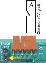
The picture above shows the jumper in the NPN position and a switch wired into the input in NPN mode. In NPN mode the switch must complete a connection between the input pin and circuit common (0V) for the input to be read as ON. The yellow arrow indicates the position of the selection jumper. The input current is
I(in) = – V(supply) / 10000
The leading minus sign simply means the current is flowing out of the pin. The 10000 represents the 10K input pullup resistance.
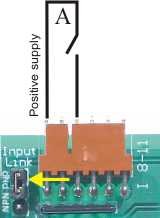
The picture above shows the jumper in the PNP position and a switch wired into the input in PNP mode. In PNP mode the switch must complete a connection between the input pin and the power supply positive terminal for the input to be read as ON. The input current is
I(in) = V(in) / 10000
V(in) is the externally applied voltage, which normally will be equal to the supply voltage. The 10000 represents the 10K input pullup resistance.
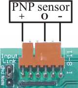
The final picture, above, shows a PNP type sensor connected to the MS120. The sensor is powered off the input connector. ‘+’ on the sensor is it’s positive power Please refer to the sensor manufacturer’s technical data for the proper connections on the sensor.
Why have 2 different ways of doing it?
The reason we have 2 different ways are largely historical. NPN and PNP refer to the two basic types of bipolar transistor. Sensor manufacturers usually make sensors in both polarities, or sometimes they make sensors that can be used as either. It tends to cost less to make a NPN outputs (like our standard transistor outputs on SPLat) because modern bipolar transistor technology is biased in favor of NPN.
Which way is best?
Which of the two is best depends on your point of view. We have a preference for NPN because it makes designs a little easier and less expensive to make, so we can bring you more functionality per dollar. On the other hand, it is argued in some quarters that PNP is safer because an accidental short circuit to ground (the most probably kind of accidental short) is less likely to produce a spurious input. The validity of this argument will depend on the specific application.
We suggest that unless you have good reason otherwise, you use the NPN mode. This will improve your chances of making a control design that is capable of transferring to our other controllers (which at time of writing all use NPN).
Threshold voltages
The actual threshold voltage is nominally about 4.6V in either mode (min/max = 3/7) . In NPN mode anything less than the threshold is On. In PNP mode anything greater than the threshold is On. The processor knows the mode because the mode jumper is fed into an auxiliary processor input.
How to blow up the dedicated inputs
- Apply more than ±35V steady state for more than 10s to any one input.
- Apply more than ±100V momentarily