MS120: Power supply
The power supply scheme on the MS120 is quite novel, and very versatile. It features:
- 2 separate supply inputs with “OR” diodes.
- The ability for your program to monitor the voltage on either supply input as an analog input.
- A jumper (link) to select between two power-down modes.
- Future feature: A low power mode for the controller (processor)
What this all means is that you can implement a range of backup, shutdown and standby schemes.
Basic operation
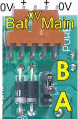
For normal, “everyday” operation without any fancy features, simply connect a 10-24VDC power supply to the terminals labeled “Main” and “+” and “0V” in the above picture, and place the jumper in position ‘A’. Please see the article on common terminology for an explanation of the labeling.
Supply voltage
In general, the MS120 needs a supply voltage between 10VDC and 24VDC. The voltage is allowed to go to a maximum of 32V. Note that the MS120 operating temperature ratings depend on the supply voltage.
It’s quite OK to use an unregulated power supply. Just remember that the ripple will make the voltage instantaneously less than the average DC value, and the board will respond to the instantaneous value. Remember, too, that an unregulated supply can go quite a bit higher than its nominal value, especially when lightly loaded and if the mains voltage is high.
If you are using any add-on boards with the MS120, for example a SPice board, you must take their power supply requirements into account. For example, the thermistor function on the SPice 10200 contains a programmable drive voltage that can go up to 20V. If you are using that function you must use a supply voltage at least 2V more than the thermistor drive voltage you are going to program.
We generally suggest customers buy an off the shelf 24V switchmode power supply. These are so inexpensive these days that it is uneconomic to do otherwise.
Supply current
The current drawn by the board will depend on the supply voltage, what the board is doing and on any add-ons. Allowing 15mA for a SPice board and 19mA for the LCD and backlight, maximum supply current draw versus supply voltage is:
| Voltage | Max current | Temp |
|---|---|---|
| 10V | 101mA | 70°C |
| 12V | 104mA | 70°C |
| 15V | 109mA | 70°C |
| 18V | 113mA | 70°C |
| 24V | 123mA | 60°C |
| 28V | (129mA) | (47°C) |
| 32V | (135mA) | (33°C) |
The temperature column gives you the maximum allowable ambient temperature for operation of the power supply regulator. Note that other considerations, especially the digital output loading, may limit operation to lower temperatures. These figures are calculated based on everything being on at once. The figures do not include any external loads such as relays. You can deduct 19mA if the LCD is not fitted.
| Note: Figures at 28V and 32V are given for reference only. We do not recommend operating the board at voltages over 24V for sustained periods of time. The board can be damaged if the power supply voltage goes over 32V, even momentarily. |
Analog input monitoring of supply voltages
The two supply voltages can be measured by the controller as analog inputs. In both cases the input is scaled to 32.77V full scale (255 counts). That means that 24V will be 255*24/32.77=186.75 counts (which will come out as 186 or 187). With this you need to take into account an overall accuracy of about 5%, so in fact you could wind up with a reading of between 177 and 196.
The “Main” power input is read with an AnInA instruction, leaving the result in X. The “Bat” input is read with an AnInB instruction.
Advanced modes
The idea of having two power inputs, and monitoring them as analog inputs, is that you can implement various power management schemes.
With the jumper in the “A” position the two power input pins are interchangeable. However, if you set the jumper in the “B” position (illustrated above), they become different. In that mode, the actual processor chip will be powered from either supply pin but the “+” connections on the I/O connectors will only be powered from the “Main” power input.
What this means is that you can connect a battery to the “Bat” supply and power the board from a normal power supply. Providing the battery voltage is less than the power supply voltage, the power supply will provide power as long as it is operating. If the power goes off, however, the battery will take over and provide power to the processor but not to the I/O connector “+” pins. Assuming you have connected your output loads to the “+” pins of the I/O connectors, the loads will be powered down if mains (line) power fails, but the processor will still receive power. This will result in a reduced power consumption while running off battery. If your program is monitoring the power supply inputs it can then shut down the LCD backlight to reduce power consumption and then wait for the main power to be restored.
Other variations are possible. It is all a matter of what you may wish to achieve. Here are some ideas:
Rechargeable battery. A resistor and diode in series can trickle charge the battery off the main power supply. The diode prevents the battery from discharging back into the power supply.
Capacitor. Use a large value capacitor on the “Bat” terminal, charge it via a diode. A 1000µF capacitor will give about about 0.5s “holdup” if charged to 24V (assuming the jumper is in the “B” position so the capacitor is not powering external loads). That would be plenty of time to memorize the machine state in permanent memory.