SPice10211: Analog inputs
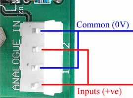
The picture above shows the connector used for analog inputs. An input is configured by using one of the supplied jumpers to bridge certain pins.
Note: Which actual analog inputs and outputs the board maps to depends on which model of SPLat controller it is attached to. The mapping is detailed under Programming.
There are two analog input channels on the SPice10211 board. Each input can be configured to operate on 0-10V, 0-20mA or as a temperature measuring input (using an external thermistor sensor). In all cases the input uses one input pin and one common pin. The common pins on the analog input connector are tied to the board’s 0V terminal. Please see the article on common terminology for an explanation of the 0V terminal.
Each channel has a 4-pin configuration jumper field. A single jumper (shunt) on a pair of jumper pins selects the operating mode (V=voltage, I=current or T=temperature). In the above picture channel 2 is set for temperature and channel 1 is set for current.
Using voltage mode
To use an analog input in voltage mode you set its jumper to bridge the two pins either side of the letter V and apply the input voltage between the input (positive) and the common (most negative). When an AnIn* instruction is executed, you will get a number between 0 and 255 in the X-register. 0 represents 0V and 255 represents 10V.
From dialect 18 you can also use the fAnIn instruction. This will return a normalized floating point number in W which ranges from 0 at 0V in to 1.000 at 10V in. The range 0 to 1.0 is divided into 1023 steps of 0.00097752 (on older controllers, viz MMi200, MMi201, MS12, the range is divided into 255 equal steps of 0.0016334). fAnIn selects the required channel with a numeric argument. Channel number are identified under programming. The channel number is jndexed.
In voltage mode the input resistance is 200KOhm.There is an input noise filter comprising a single RC time constant of 5mS.
If you leave the jumper out, you will get a 0-5V range instead of 0-10V.
Using current mode
To use an analog input in current mode you set its jumper to bridge the two pins either side of the letter I. You then feed the current to be measured into the input pin, with the return out of the common pin.
When an AnIn instruction is executed, you will get a number between 0 and 255 in the X-register. 0 represents 0mA and 255 represents 20mA. At 4mA you will get a reading of 51 (plus or minus any conversion error). You can also use fAnIN, which will return 0 for 0mA, 1.0 for 20mA and 0.2 for 4mA (plus or minus any conversion error). fAnIn selects the required channel with a numeric argument. Channel number are identified under programming.The channel number is jndexed.
In current mode the input resistance is 250Ohms. There is an input noise filter comprising a single RC time constant of 10mS.
Accuracy and resolution (voltage and current modes)
The accuracy is about 1.5% of full scale. Resolution is 10-bit (0.1% of full scale) on late model controllers. On older controllers, viz MMi200, MMi201, MS12, the resolution is 8-bit (0.4% of full scale).
Using thermistor mode
To use the analog input in temperature mode you set its jumper to bridge the two pins either side of the letter T and connect a suitable thermistor between the analog input pin and common. There are two basic types of thermistor: Positive Temperature Coefficient (PTC) and Negative Temperature Coefficient (NTC). The latter, NTC, is the type used for temperature measurement with SPLat. Typically, an NTC thermistor is specified as having a certain resistance at 25 degrees C.
The adjacent diagram shows the thermistor measuring circuit.
The thermistor is the bottom resistor in a voltage divider. The top resistor is a fixed onboard 10.25KOhm resistor. The voltage divider is driven by a programmable voltage that appears as analog output 8. This is an “onboard output” that is used for thermistor drive and is also available on the SPice connector, but does not “use up” either of the two externally available analog outputs. The thermistor drive voltage can be set to anything between 0V and 20V. Note that the board supply voltage must be at least 2V greater than the intended drive voltage. The drive voltage is programmed using an fAnOut instruction to the appropriate channel defined under programming. With W=0 this will result in 0V out, with W=1 it will result in 20V out.
In this thermistor mode the full scale analog input voltage is 5V (whereas the thermistor output drive has a full scale of 20V).
A thermistor is an electronic component that changes resistance with temperature. Don’t confuse this with an RTD sensor, which also changes resistance with temperature but is much less sensitive! The warmer the thermistor gets, the lower its resistance. Hence, a reading of the input voltage can be used to calculate the thermistor temperature.
Accuracy and resolution depend on the thermistor you use and how you program it. The best achievable figures are about 0.2°C for both, if the system includes provision for software calibration. The SPLat Knowledge Base contains a tutorial on thermistor temperature measurement using SPLat boards.
How to blow up the analog input
Here are some ways of blowing up the analog inputs:
- In any mode, connect the input to a voltage greater than the positive supply or negative with respect to the 0V terminal.
- In current mode, apply more than 7.5V to the input. This will overheat the current shunt resistor and lead to loss of accuracy or, in the extreme, damage the board.
Analog inputs and SPLatLink
The board is capable of returning analog readings via SPLatLink without any specific provisions on your part.