RTD template
The RTD Active Template lets you use Platinum Resistance Detector (RTD) temperature sensors on the standard thermistor analog inputs on MMi202 or SL100 controllers and optional SPice 10200 and SPice10211 add-on boards. It also covers the MS120 with the same SPice boards (the MS120 must have a SPice board for analog input). We advise against trying this with earlier controller models, as they did not have sufficient analog resolution for this to work.
The resistance of the RTD is measured using our standard thermistor configuration. The RTD and a fixed 10250 Ohm resistor on the board form a voltage divider. A programmable drive voltage up to 20V is applied to the divider and the voltage developed across the RTD is measured. This is then used to calculate the RTD resistance, and from that its temperature. This is a rough and ready method. At very low cost it will give you a reading of modest accuracy, and it can be extended to temperatures where thermistors are no very effective. An example application would be in bakers’ ovens that need to operate up to 300°C with an accuracy of say 5°C.
The main limitations of this method are:
- Sensor self-heating. The voltage/current applied to the RTD sensor are relatively high and there will be some self-heating of the sensor. The template allows for some compensation of this, if you can determine the sensor’s self-heating factor, and provides an estimate of its magnitude. This is more of an issue in still-air than say in liquids.
- Connecting lead resistance. Ideally an RTD sensor will be operated in 3-wire or 4-wire mode, where the effect of connecting wire resistance is eliminated. That is unfortunately not possible with our thermistor connection. The template lets you compensate for connecting lead resistance and displays its magnitude.
- Resolution. Resolution is the ability to detect small changes (not to be confused with accuracy!). This method provides modest resolution rather than high resolution.
- Electronic Accuracy. This is a measure of the difference between a resistance reading and the true value. In our circuit the main determiner is the 1% accuracy of the 10250 Ohm resistor that feeds the RTD (everything else is ratiometric). A 1% tolerance of that resistance would lead to about 2.4°C error in temperature, though in practice 1% resistors are typically much better.
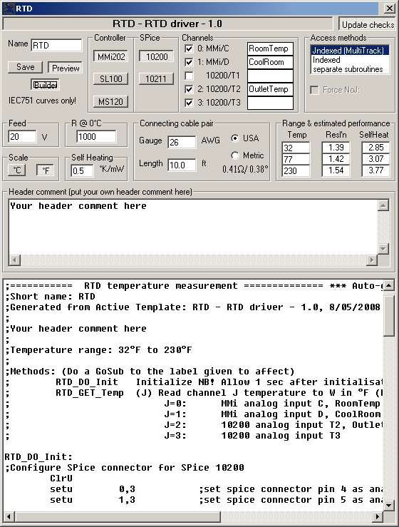
The template settings are:
Name box
When you Save your altered template and settings, the file produced will have this name with the extension .tp1. The name will also be used in all the program labels in the generated code, including the subroutines used to access the code generated by the template. If you change Name then all subroutine names will change.
Save button
Saves the current settings in a template file named whatever you have set in the Name box
Builder button
When depressed, the code generated will contain Builder tags. SPLat Active Templates are designed primarily to be used with Builder. Builder gives you the ability to make your programs modular, with the various module (files) only being linked together into a single SPLat program late in the process. This template optionally inserts Builder segment tags into the generated files. You should study the code in the preview window to determine which tags you must specify in your build (*.b1d) file and how to qualify them (e.g. ONCEONLY).
Preview button
Opens and closes the code preview pane
Controller
Lets you select the controller type that you are using.
SPice
Lets you select which (if any) SPice board you are using.
Channels
As you change the controller and SPice board combination, this box will automatically list the available analog inputs in a series of check boxes. You can now select which of the available ones you want to use. When you select one, it is assigned a numeric channel number. The checkbox label is automatically set to show a channel number, a colon and a brief description of the input couched to reflect the physical markings on the actual board. For example
2: 10200/T2
means that the T2 input on the SPice10200 board has been assigned channel number 2.
Access method
If you select 2 or more channels, you have a choice of how to extract your readings.
| jndexed | Assuming you fully understand MultiTrack and the use of the J register for jndexed addressing, you can take advantage of the jndexed mode of the template. You will get one subroutine to call for all channels. The number in J determines which channel will be returned, 0 or 1.Caution: The code does not check that I contains a valid value |
| indexed | In indexed mode you get one subroutine to call for both channels. The number in I determines which channel will be returned.Caution: The code does not check that I contains a valid value |
| separate subroutines | If you select this mode you will get a separate subroutine for retrieving readings from each of your selected channels. |
You can determine what subroutine name(s) to call from the generated code in the preview window.
Force NoJ
Inserts NoJ: precodes on all potentially jndexed instructions. Select this option if you are calling (GoSub-ing to) the template code from jndexed MultiTrack tasks, but not using the jndexed access method. It will do little harm (simply slow things down ever so slightly) to check the box unnecessarily if you are not using jndexing.
Feed
This is the feed voltage used to drive the RTD sensor. It must be less than 20V.
R @ 0°C
This is the 0°C resistance of the RTD sensor. Common values are 100Ohm (called Pt100) and 1000Ohm (Pt1000). You should use Pt1000. Pt100 will produce poor results. Some vendors also offer Pt2000 and Pt10000. These will give better resolution at the cost of more self-heating. In a liquid, where self heating is less, that may be a workable trade-off.
Note that the template works only with IEC751 curve sensors (the most common type in America, Europe and Australasia). For all practical purposes this also covers DIN43760.
Scale
Allows you to select between the result being scaled in ºC or ºF.
Self heating
This box lets you enter the thermal resistance or self-heating coefficient of the sensor you are using, if the manufacturer provides it. Self heating is significant mainly in still air applications, and if the sensor data provides a figure it will normally be for still air conditions. The figure will then not apply to moving air or liquids.
The self heating may be specified in degrees per milliwatt or milliwatts per degree (the reciprocal). The degree scale used is generally °K or °C, which in this situation are equivalent. The template lets you enter the number in °K/mW. A typical number quoted for small sensor elements is 0.5°K/mW.
If you leave the box empty or containing zero, there will be no compensation for self heating.
Connecting cable pair
This lets you enter the length and gauge of the cable connecting the sensor to the board. You can use US units or metric units. Enter the length of the one way length, not the loop (there and back) length.
Range and estimated performance
This lets you enter the range of temperatures you are going to be measuring and gives you an estimate of two performance factors, resolution and self-heating, taking into account all the settings you have entered. You must set the top and the bottom temperature values (the middle one is optional). The template uses these to compute the optimum equation to use (a 3rd order polynomial) for converting resistance into temperature. The estimated performance figures let you explore the effect of the various settings.
Update checks
If the button in the top righthand corner is depressed, the template will automatically check online for any updates whenever it is run, assuming you have a live Internet connection.
Header comment
You can type whatever you like into this box. It will appear in the generated code as a comment near the top.