ModBus master scripts: A worked example
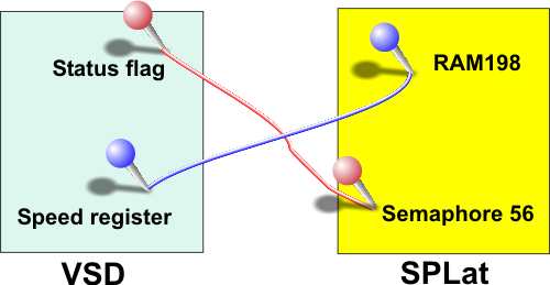
As an example, let’s go through the steps to set up the connections illustrated in the above diagram. The SPLat is to be the master and the VSD is to be the slave.
Step 1: Determine resource addresses and data types
We have already determined the addresses in SPLat, as they are given in the diagram. Stated verbally “we want the value in SPLat’s RAM location 198 to control the speed of the VSD, and we want the VSD’s status flag to be available as semaphore 56″. Hence RAM 198 must be written from the SPLat to the VSD, and semaphore 56 must be read from the VSD.
In our example we need to establish the addresses within the VSD. That information must come from the VSD documentation.
Let’s say that the VSD manual gives the speed register address as 41234 and the status flag as 00025. These addresses tell us that the speed register is mapped as a holding register (4xxxx) and the status flag as an internal coil (0xxxx). By implication the VSD maker is using Modicon references. These are presumably 1-based addresses (a thoughtful vendor will state that quite explicitly somewhere in their documentation)
We can now make up the following chart:
| Variable | VSD address | ModBus address | SPLat address | Transfer type | Direction |
|---|---|---|---|---|---|
| VSD speed | 41234 | 1233 | RAM 198 | Holding reg | SPLat to VSD |
| VSD status | 00025 | 24 | Sem 56 = Byte 7 bit 0 | Coil | VSD to SPLat |
Step 2: Decide what ModBus messages to use
No equipment maker supports every ModBus function type in every product. You therefore need to compare the supported function lists for SPLat and for the other device and find appropriate functions supported in both. This is why we have provided some redundancy in the functions we support, to improve the odds of you finding suitable matches.
In the current example the choices will be either function 6 (preset single holding register) or 16 (preset multiple holding registers) for speed, and function 1 (read coil(s)) for the status. Assuming the VSD supports 6, we select that as the simplest of the two.
Step 3: Decide on word mode or byte mode for register transfers.
This is an important point, as it concerns matching the 8-bit world of SPLat to the 16-bit world of ModBus. In the current example we are sending a single byte variable to a 16-bit register, so byte mode is the best choice (it will force the high order byte to 0 automatically).
Step 4: Determine the slave address
Every ModBus device other than the master must have an address. You must consult the VSD documentation to find out how to set its address. Valid addresses are 1 to 247. Assume we set the VSD to 123. The VSD documentation will tell you how to do this (probably via DIP switches or a front panel setting)
Step 5: Write the control script
Once we are this far the hard part is done. The decisions are made and we simply have to encode them into some numbers.
We will write a script that simply runs indefinitely, looping back on itself. That means the SPLat master will generate continuous update messages and keep the VSD and its own memory in step. We call this “continuous and asynchronous”, because the communications updates take place all the time, and without regard to anything else going on in the SPLat program or the VSD. It is the simplest thing to do. The downside is that there will be variable delays between the SPLat say changing the speed in RAM 198 and the VSD receiving the changed value. You can make “one shot, synchronous” scripts as well, but it is more difficult.
The script will have to specify two ModBus functions, a function 6 for the speed and a function 1 for the status. The hot links in the previous sentence are to the relevant script commands.
The function 6 script command requires: Function number (6), SlaveAddr (123), RegAddr16 (1233), SPAddr16 (56) and SPMode (0). Hence, the script entry for the function 6 will be
NV0Byte 6,123,#1233,#56,0
This entry will eventually be placed in the NVEM0 section of your program. The # characters signal a 16-bit entry.
The function 1 script command requires: Function number (1), SlaveAddr (123), CoilAddr16 (24), ItemCount(1) and SPAddr16 (198). Hence, the script entry for the function 1 will be
NV0Byte 1,123,#24,1,#198
In order to make this script run continuously we need a GoTo script command and a label to target. Putting it all together we get:
NVEM0 ;Start of NVEM page 0 data. ;This is my very first ModBus script! ModBusScript: ;A target label for the GoTo NV0Byte 6,123,#1233,#56,0 ;Function 6, set the speed NV0Byte 1,123,#24,1,#198 ;Function 1, read the status NV0Byte 128 ;GoTo opcode: Loop forever NV0Ptr ModBusScript ;GoTo targetBe very careful to get the # in all the arguments that are specified as 16-bits in the script definitions. Double check! A mistake here could be very hard to debug.
Step 6: Set up the Communications Control Block (CCB)
Before the SPLat can communicate in ModBus, it needs have the correct communications parameters set up. This is done through the Communications Control Block (CCB). This is documented elsewhere. To set up a CCB you need to study the documentation for all the devices in your system and settle on a set of parameters that will work for them all and also with the communications channel (be it a direct wire hookup or a laser bounced off the moon).
The CCB is stored in NVEM page 0 along with the ModBus command script. Here is a typical CCB for a ModBus master:
ModBus_CCB: ;Communications Control Block for ModBus master NV0Byte 2 ;Protocol = ModBus RTU Master NV0Byte 0 ;Device address (N/A) NV0Byte 0 ;Character profile (8,N,1) NV0Byte 7 ;Baudrate = 38400 NV0Byte 255 ;Not used - set to 255 NV0Byte 255 ;Not used - set to 255 NV0Byte 255 ;Not used - set to 255 NV0Byte 255 ;Not used - set to 255 NV0Byte 255 ;Not used - set to 255 NV0Byte 5 ;Message gap x 10mS NV0Byte 15 ;Query timeout x 10mS NV0Byte 3 ;Query attempts before failure NV0Byte 255,255,255,255,255,255,255,255, ;Not used - set to 255
There is a ModBus CCB work sheet here.
Step 7: Invoke!
All that is left to do is to have your SPLat program execute the right instructions to invoke the CCB and to start the control script running. This would normally be done near the start of your program, during initialization. The instructions for this are:
;Get the ModBus communications going. ComSetCCB ModBus_CCB ;Point processor at CCB for ModBus ComRunScript ModBusScript ;Start the comms control scriptOnce those two instructions are executed, the script will start running and simply do its job, fully automatically, in the background. Note that for the first 10 seconds after startup SPLat cannot switch protocols, so the ComSetCCB may cause a delay (depending on how you use it).