PIDassist: Display
PIDassist features an oscilloscope style display and a basic data logging facility.
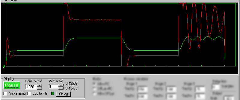
The green trace is the output of the process. The red trace is the output of the controller. There are 20 horizontal divisions. At the fastest Horizontal rate there are 500 samples per screen width, more at slower rates.
The Pause button stops the simulation and pauses the display. It is shown above in the “unpaused” state, meaning the simulation is running.
Horiz. S/div sets the horizontal time base. Note that the available settings are multiples of the sampling interval (which is set in the controller pane). The scale will change when you change the sampling interval. During simulation the scale is Seconds/division. During operation in a SPLat board the scale is Samples/division (in that mode the SPLat board sets the pace).
Vert scale sets the vertical scale factor for both traces. It can go down to 1 as show and up to silly numbers. You would normally use it on 1, or maybe on 2 if the process output is peaking at more than 1 (because nearly everything is in the normalised range 0 to 1).
Anti-aliasing can sometimes get rid of artificially produced low frequency signals (the mechanism is the same one that makes the wagon wheels go backwards on old cowboy movies). We use a min/max algorithm. If you find a periodic wave appears as you slow down the time base, it may be aliasing. Turn on anti-aliasing and see if it goes away.
Log to file turns on logging. All data points (every sample) are written to a comma delimited (*.csv) file that can be read by Excel. The default file name is default.csv. You can change the file name via the File menu. The green “LED” flashes each time a sample is logged. Note that every sample is logged, so you could wind up with a very large file! The file format consists of two columns of data. The first one is the process output and the second one is the controller output.
Clr log simply clears the log file. There are no annoying “Are you sure?” boxes, so beware.
To the right of the Vert scale control are two numbers. The top one is the raw process output. The bottom one is the same data fed through an adaptive low pass filter so you can better see the average of a value that is jittering or oscillating slightly. It pays to look at these numbers from time to time, because a simulation can look very stable but have settled at an incorrect value due to inappropriate settings.