Knowledge Base
- 0.1" Connectors
- HMI700 3.3V Calibration
- HMI430/700: I/O Map (Source Code)
- HMI - Simple Example
- HMI430: Technical specification
- HMI430: EMC Report
- HMI700: EMC Report
- HMI430/700: USB Driver
- HMI430/700: File System
- HMI430/700: Power supply
- HMI430/700: OnBoard Counter type A (OBCA)
- HMI430/700: OnBoard Counter type B (OBCB)
- HMI430/700: Beeper
- HMI430/700: Crosshairs
- HMI430/700: Touchscreen calibration
- HMI430: Fitting into your product
- The CPU device
- CPU: Firmware revision
- CPU: Dialect
- CPU: Board type
- CPU: I/O configuration
- CPU: Subroutine nesting depth
- CPU: Runtime error codes
- CPU: Processor reset flags
- CPU: DTR input
- CPU: Miscellaneous resources (D>=16)
- CPU: RTS output
- CPU: Altering SuperTimer 10mS timebase [D>=20]
- CPU: Processor temperature
- MMi203: Power supply
- MMi203: Real Time Clock
- MMi203: OnBoard Counter type A (OBCA)
- MMi203: OnBoard Counter type B (OBCB)
- MMi203: OnBoard Quadrature Counter (OBQC)
- MMi202: CPU device
- MMi203: CPU device
- MMi99: CPU Device
- MMi203: Option links
- MMi203: SPice connector
- MMi203: Xwire
- MMi202: Comms connector
- MMi203: Comms connector
- MMi203: Communications
- MMi203: MultiTrack
- MMi203: Operating temperature ratings
- CC16 product documentation
- DR8 product documentation
- DW2 Product Documentation
- MMi99 Product documentation
- MMi200 product documentation
- MMi201 Product documentation
- MMi202 Product documentation
- SL99 product documentation
- The CPU device
- CPU: Firmware revision
- CPU: Dialect
- CPU: Board type
- CPU: I/O configuration
- CPU: Subroutine nesting depth
- CPU: Runtime error codes
- CPU: Processor reset flags
- CPU: DTR input
- CPU: Miscellaneous resources (D>=16)
- CPU: RTS output
- CPU: Altering SuperTimer 10mS timebase [D>=20]
- CPU: Processor temperature
- CPU: Unique ID
- 32bit Controller Enhancements
- iiChrPrintX dest# [D>=23]
- DecI
- DecM mm+
- DecX
- DecMGoIfNZ mm*+,LLLL
- DecMRetIfNZ mm+
- DecMRetIfZ mm+
- DMGNZ mm*+,LLLL
- fDec
- fInc
- iifPrintWVW dest#,f,p [D>=23]
- iifPrintWFW dest#,f,p [D>=23]
- GetCount7 [D= 4 to 15]
- iiHexPrintX dest# [D>=23]
- IncI
- IncM mm+
- IncX
- OBCA_fRead
- OBCA_GoIfNoRdg line
- OBCA_GoIfRdg line
- OBCA_Mode m
- OBCA_RetIfNoRdg
- OBCA_WaitRdg
- OBCB_GoIfA LLLL
- OBCB_GoIfB LLLL [D>=19]
- OBCB_fRdClr c+ [D>=19]
- OBCB_fRead c+ [D>=19]
- OBCB_Start c+ [D>=19]
- OBCB_StartA c [D>=19]
- OBCB_Stop c+ [D>=19]
- OBCB_StopB c+ [D>=19]
- OBQC_Clr c [D>=16]
- OBQC_fGet c [D>=16]
- OBQC_fSet c [D>=16]
- OBQC_Status c [D>=17]
- iiPrintFill dest#,count,value [D>=23]
- iisPrintXFW dest# [D>=23]
- iisPrintXVW dest# [D>=23]
- iiuPrintXFW dest# [D>=23]
- iiuPrintXVW dest# [D>=23]
- SetCount7 [D= 4 to 15] DEPRECATED
- ModBus: Resource mapping
- ComDevAddr [D>=17]
- aComDevAddr pp [D>=29]
- ComHaltScript [D>=17]
- ComResumeScript [D>=17]
- ComRunScript pppp [D>=17]
- MODBUS Number Format
- ReadCoil(s) - 1, SlaveAddr, CoilAddr16, ItemCount, SPAddr16
- ReadInputs - 2, SlaveAddr, InAddr16, ItemCount, SPAddr16
- ReadHregs - 3, SlaveAddr, RegAddr16, ItemCount, SPAddr16, NumFormat
- ReadInRegs - 4, SlaveAddr, InRegAddr16, ItemCount, SPAddr16,NumFormat
- ForceCoil - 5, SlaveAddr, CoilAddr16, SPAddr16
- PresetHreg - 6, SlaveAddr, RegAddr16, SPAddr16, SPMode
- ForceMultCoils - 15, SlaveAddr, CoilAddr16, ItemCount, SPAddr16
- PresetMultRegs - 16, SlaveAddr, RegAddr16, ItemCount, SPAddr16, SPMode
- GoTo - 128, NVPtr16
- Stop - 129
- Delay - 130, Time
- Com_Flags [D>=23]
- ComRx_BufLen [D>=23]
- ComRx_DelXChars [D>=23]
- ComRx_FindXInBuf (X) [D>=23]
- ComRx_fGetNum fw [D>=26]
- ComRx_GetHex [D>=23]
- ComRx_Peek (X) [D>=23]
- ComRx_ReadOne [D>=23]
- ComTx_Space [D>=23]
- ComRx_StrFind c [D>=27]
- ComRx_StrFind2 c [D>=29]
- ComRx_Trim (X) [D>=23]
- ComTestStartTimer [D>=17]
- ComSetCCB pppp [D>=17]
- aCom_Flags pp [D>=29]
- aComRx_BufLen pp [D>=29]
- aComRx_DelXChars pp [D>=29]
- aComRx_FindXInBuf (X) [D>=23]
- aComRx_fGetNum pp,fw [D>=29]
- aComRx_GetHex pp [D>=29]
- aComRx_Peek pp [D>=29]
- aComRx_ReadOne pp [D>=29]
- aComRx_StrFind pp,c [D>=28]
- aComRx_StrFind2 pp,c [D>=29]
- aComRx_Trim pp [D>=29]
- aComTx_Space pp [D>=29]
- aComSetCCB pp,nnnn [D>=29]
- iFindXInBuf bb*,nn [D>=28]
- iiChrPrintX dest# [D>=23]
- iifGetNum bb#,nn,fw [D>=28]
- iifPrintWFW dest#,f,p [D>=23]
- iifPrintWVW dest#,f,p [D>=23]
- iiGetHex bb#,nn [D>=28]
- iiHexPrintX dest# [D>=23]
- iiPrintFill dest#,count,value [D>=23]
- iiPrintNVText dest# [D>=27]
- iiPrintText dest#,text-string [D >= 23]
- iisPrintXFW dest# [D>=23]
- iiStrFind bb#,nn,c [D>=28]
- iiStrFind2 bb#,nn,c [D>=29]
- iiuPrintXFW dest# [D>=23]
- iiuPrintXVW dest# [D>=23]
- iisPrintXVW dest# [D>=23]
- aComRx_fGetNum pp,fw [D>=29]
- ComRx_fGetNum fw [D>=26]
- fAbs
- fAdd
- fAnIn c+ [D>=18]
- fAnOut c+ [D>=18]
- fCompareR
- fDec
- fDiv
- fGetTimer t
- fGoIfNeg LLLL
- fGoIfNZ LLLL
- fGoIfPos LLLL
- fGoIfWGEQ LLLL [D>=23]
- fGoIfWGTQ LLLL [D>=23]
- fGoIfWLEQ LLLL [D>=23]
- fGoIfWLTQ LLLL [D>=23]
- fGoIfZ LLLL
- fIEEEtoWR [D>=21]
- fInc
- fix
- FixToMem16S mm* [D>=21]
- FixToMem16U mm+ [D>=21]
- fLoadQ ffff
- fLoadW ffff
- float
- FloatMem16S mm* [D>=21]
- FloatMem16U mm+ [D>=21]
- fMul
- fNeg
- fPulse0 [D>=19]
- fRecallQ mm*+
- fRecallW mm*+
- fSetTimer t
- fSign
- fStore mm*+
- fSTSinceMark [D>=22]
- fSTTimeSince aa+ [D>=16]
- fSub
- fSwap
- fTest
- fTestWeqQ [D>=24]
- fTestWeqZ [D>=25]
- fTestWgeQ [D>=25]
- fTestWgeZ [D>=25]
- fTestWgtQ [D>=25]
- fTestWleQ [D>=25]
- fTestWltQ [D>=25]
- fTestWltZ [D>=25]
- fTestWneQ [D>=25]
- fTestWneZ [D>=25]
- fWtoQ
- fWtoIEEER [D>=21]
- iifGetNum bb#,nn,fw [D>=28]
- iifPrintWFW dest#,f,p [D>=23]
- iifPrintWVW dest#,f,p [D>=23]
- NVfGetEndW [D>=15]
- NVfGetPtrW [D>=15]
- NVfGetRecNumW [D>=15]
- NVfPutPtrW [D>=15]
- NVfPutRecNumW [D>=15]
- NVfReadQ nn*+ [D>=15]
- NVfReadW nn*+ [D>=15]
- NVfWriteW nn*+ [D>=15]
- OBCA_fRead
- Result codes for fAdd, fSub, fMul, fDiv
- Result codes for fCompareR
- Result codes for fInc, fDec
- Result codes for fix
- Result codes for fSetTimer
- Result codes for fTest
- Branch
- BranchJ [D>=16]
- BranchM mm+
- BranchR
- DecMGoIfNZ mm*+,LLLL
- DecMRetIfNZ mm+
- DecMRetIfZ mm+
- fGoIfNeg LLLL
- fGoIfNZ LLLL
- fGoIfPos LLLL
- fGoIfWGEQ LLLL [D>=23]
- fGoIfWGTQ LLLL [D>=23]
- fGoIfWLEQ LLLL [D>=23]
- fGoIfWLTQ LLLL [D>=23]
- fGoIfZ LLLL
- GoIfF LLLL
- GoIfInK ii+,LLLL
- GoIfInOff ii+,LLLL
- GoIfInOn ii+,LLLL
- GoIfINZ LLLL
- GoIfIZ LLLL
- GoIfMEQ mm+,nn,LLLL
- GoIfMGE mm+,nn,LLLL
- GoIfMGT mm+,nn,LLLL
- GoIfMLE mm+,nn,LLLL
- GoIfMLT mm+,nn,LLLL
- GoIfMNE mm+,nn,LLLL
- GoIfMNZ mm+,LLLL
- GoIfMZ mm+,LLLL
- GoIfNZ LLLL
- GoIfRTCEvent e+,LLLL [D>=16]
- GoIfSF ss,bb+,LLLL [D>=12]
- GoIfSim LLLL
- GoIfST ss,bb+,LLLL [D>=12]
- GoIfT LLLL
- GoIfUF n,m,line
- GoIfUT n,m,line
- GoIfXEQ nn,LLLL
- GoIfXGE nn,LLLL
- GoIfXGT nn,LLLL
- GoIfXLE nn,LLLL
- GoIfXLT nn,LLLL
- GoIfXNE nn,LLLL
- GoIfZ LLLL
- GoSub LLLL
- GoSubIfF LLLL
- GoSubIfMNZ mm+,LLLL
- GoSubIfMZ mm+,LLLL
- GoSubIfNZ LLLL
- GoSubIfST ss,bb+,LLLL [D>=12]
- GoSubIfT LLLL
- GoSubIfXEQ nn,LLLL
- GoSubIfXGE nn,LLLL
- GoSubIfXGT nn,LLLL
- GoSubIfXLE nn,LLLL
- GoSubIfXLT nn,LLLL
- GoSubIfXNE nn,LLLL
- GoSubIfZ LLLL
- GoTo LLLL
- OBCA_GoIfNoRdg line
- OBCA_GoIfRdg line
- OBCA_GoSubIfRdg line
- OBLCD_GoIfBusy line
- OBLCD_GoIfIdle line
- RetIfF
- RetIfMNZ mm+
- RetIfMZ mm+
- RetIfNZ
- RetIfT
- RetIfZ
- Return
- Suspend mm*+ [D>=12/15]
- Target LLLL
- #IF, #ELSEIF, #ELSE, #ENDIF (Conditional code translation)
- ClrS ss+,bb* [D>=12]
- DecI
- fRecallQ mm*+
- fRecallW mm*+
- fStore mm*+
- GoIfINZ LLLL
- GoIfIZ LLLL
- iiChrPrintX dest# [D>=23]
- iifPrintWFW dest#,f,p [D>=23]
- iifPrintWVW dest#,f,p [D>=23]
- iiHexPrintX dest# [D>=23]
- iiPrintFill dest#,count,value [D>=23]
- iiPrintNVText dest# [D>=27]
- iiPrintText dest#,text-string [D >= 23]
- iisPrintXFW dest# [D>=23]
- iisPrintXVW dest# [D>=23]
- iiuPrintXFW dest# [D>=23]
- iiuPrintXVW dest# [D>=23]
- IncI
- Input ii*+
- InputF ii*+
- InputK ii*+
- InputO ii*+
- ItoX
- LoadI nn
- Off oo*+
- On oo*+
- Output oo*+
- NotS ss+,bb* [D>=12]
- NVfReadQ nn*+ [D>=15]
- NVfReadW nn*+ [D>=15]
- NVfWriteW nn*+ [D>=15]
- NVPopByte nn*+ [D>=15]
- NVPushByte nn*+ [D>=15]
- Recall mm*+
- RecallS ss+,bb* [D>=12]
- SetS ss+,bb* [D>=12]
- ShadowRead mm*+,cc
- ShadowWrite mm*+,cc
- Store mm*+
- StoreS ss+,bb* [D>=12]
- XtoI
- Blink oo+
- BlinkM oo+
- BlinkMask mm
- fPulse0 [D>=19]
- GoIfInK ii+,LLLL
- GoIfInOff ii+,LLLL
- Input ii*+
- InputF ii*+
- InputFM ii+
- InputK ii*+
- InputM ii+
- InputMK ii+
- InputO ii*+
- InputOM ii+ [D>=13]
- InputR ii+,tt
- KBeep [D>=16]
- KBeepOff
- KBeepOn
- Off oo*+
- On oo*+
- Output oo*+
- OutputB oo+
- OutputM oo+
- ResetK
- WaitOff ii+
- WaitOffT ii+,tttt
- WaitOnK ii+
- WaitOnKT ii+,tttt
- WaitOnT ii+,tttt
- BranchM mm+
- iiChrPrintX dest# [D>=23]
- ClrS ss+,bb* [D>=12]
- ComRx_DelXChars [D>=23]
- ComRx_GetHex [D>=23]
- ComRx_ReadOne [D>=23]
- DecM mm+
- DecMGoIfNZ mm*+,LLLL
- DecMRetIfNZ mm+
- DecMRetIfZ mm+
- DMGNZ mm*+,LLLL
- iiChrPrintX dest# [D>=23]
- iifPrintWFW dest#,f,p [D>=23]
- iifPrintWVW dest#,f,p [D>=23]
- iiHexPrintX dest# [D>=23]
- iiPrintFill dest#,count,value [D>=23]
- iiPrintNVText dest# [D>=27]
- iiPrintText dest#,text-string [D >= 23]
- iisPrintXFW dest# [D>=23]
- iisPrintXVW dest# [D>=23]
- iiuPrintXFW dest# [D>=23]
- iiuPrintXVW dest# [D>=23]
- fRecallQ mm*+
- fRecallW mm*+
- GoIfMEQ mm+,nn,LLLL
- GoIfMGE mm+,nn,LLLL
- GoIfMGT mm+,nn,LLLL
- GoIfMLE mm+,nn,LLLL
- GoIfMLT mm+,nn,LLLL
- GoIfMNE mm+,nn,LLLL
- GoIfMNZ mm+,LLLL
- GoIfMZ mm+,LLLL
- GoIfST ss,bb+,LLLL [D>=12]
- GoSubIfMNZ mm+,LLLL
- GoSubIfMZ mm+,LLLL
- GoSubIfSF ss,bb+,LLLL [D>=12]
- GoSubIfST ss,bb+,LLLL [D>=12]
- IncM mm+
- NotS ss+,bb* [D>=12]
- PermRecall [D>=2]
- PermStore [D>=2]
- Recall mm*+
- RecallS ss+,bb* [D>=12]
- RetIfMNZ mm+
- RetIfMZ mm+
- RetIfST ss,bb+ [D>=12]
- SetMem mm*+,nn
- SetS ss+,bb* [D>=12]
- ShadowClear mm*+,cc
- ShadowWrite mm*+,cc
- StoreS ss+,bb* [D>=12]
- BranchJ [D>=16]
- ClrInstCount [D>=18]
- fSTTimeSince aa+ [D>=16]
- GetTick100 [D>=12]
- KillTask [D>=16]
- LaunchTask LLLL,jj [D>=16]
- LaunchTaskJ LLLL [D>=16]
- LaunchTaskX LLLL [D>=16]
- LoopIfTiming tttttt,LLLL [D>=16]
- MarkTime [D>=16]
- RunTasks [D>=16]
- RunTasksForever [D>=16]
- STScale ss [D>=16]
- STStart aa+ [D>=16]
- STTest aa+,tttttt [D>=16]
- WaitForRTCEvent e+ [D>=16]
- WaitForSF ss,bb [D>=16]
- WaitForST ss,bb [D>=16]
- YieldTask [D>=16]
- NV0Byte Directive [D>=15]
- NV0fNum Directive [D>=15]
- NV0Ptr Directive [D>=15]
- NV0Space Directive [D>=15]
- NVAddPtr nn [D>=15]
- NVAdvPtr [D>=15]
- NVDecRecNum [D>=15]
- NVEM0 Directive [D>=15]
- NVfGetEndW [D>=15]
- NVfGetPtrW [D>=15]
- NVfGetRecNumW [D>=15]
- NVfPutPtrW [D>=15]
- NVfPutRecNumW [D>=15]
- NVfReadQ nn*+ [D>=15]
- NVfReadW nn*+ [D>=15]
- NVfWriteW nn*+ [D>=15]
- NVIncRecNum [D>=15]
- NVPopByte nn*+ [D>=15]
- NVPopPage [D>=15]
- NVPopRecLen [D>=15]
- NVPopRecNum [D>=15]
- NVPushByte nn*+ [D>=15]
- NVPushPage [D>=15]
- NVPushRecLen [D>=15]
- NVPushRecNum [D>=15]
- NVReadRec mm [D>=15]
- NVReadToPtr nn [D>=15]
- NVSetPage nn [D>=15]
- NVSetPtr pppp [D>=15]
- NVSetRecLen nn [D>=15]
- NVSetRecNum nnnn [D>=15]
- NVSubPtr nn [D>=15]
- NVtoUV nn,u [D>=15]
- NVWriteRec mm [D>=15]
- OBLCD_NVText nn [D>=15]
- PermRecall [D>=2]
- PermStore [D>=2]
- ShadowClear mm*+,cc
- ShadowRead mm*+,cc
- ShadowWrite mm*+,cc
- fCompareR
- fGoIfNeg LLLL
- fGoIfNZ LLLL
- fGoIfPos LLLL
- fGoIfWGEQ LLLL [D>=23]
- fGoIfWGTQ LLLL [D>=23]
- fGoIfWLEQ LLLL [D>=23]
- fGoIfWLTQ LLLL [D>=23]
- fGoIfZ LLLL
- fTest
- fTestWeqQ [D>=24]
- fTestWeqZ [D>=25]
- fTestWgeQ [D>=25]
- fTestWgeZ [D>=25]
- fTestWgtQ [D>=25]
- fTestWleQ [D>=25]
- fTestWltQ [D>=25]
- fTestWltZ [D>=25]
- fTestWneQ [D>=25]
- fTestWneZ [D>=25]
- Result codes for fCompareR
- Branch
- BranchM mm+
- BranchR
- Compare
- CompareR
- DecMGoIfNZ mm*+,LLLL
- DecMRetIfNZ mm+
- DecMRetIfZ mm+
- DMGNZ mm*+,LLLL
- GoIfINZ LLLL
- GoIfIZ LLLL
- GoIfMEQ mm+,nn,LLLL
- GoIfMGE mm+,nn,LLLL
- GoIfMGT mm+,nn,LLLL
- GoIfMLE mm+,nn,LLLL
- GoIfMLT mm+,nn,LLLL
- GoIfMNE mm+,nn,LLLL
- GoIfMNZ mm+,LLLL
- GoIfMZ mm+,LLLL
- GoIfNZ LLLL
- GoIfXEQ nn,LLLL
- GoIfXGE nn,LLLL
- GoIfXGT nn,LLLL
- GoIfXLE nn,LLLL
- GoIfXLT nn,LLLL
- GoIfXNE nn,LLLL
- GoIfZ LLLL
- GoSubIfMNZ mm+,LLLL
- GoSubIfMZ mm+,LLLL
- GoSubIfNZ LLLL
- GoSubIfXEQ nn,LLLL
- GoSubIfXGE nn,LLLL
- GoSubIfXGT nn,LLLL
- GoSubIfXLE nn,LLLL
- GoSubIfXLT nn,LLLL
- GoSubIfXNE nn,LLLL
- GoSubIfZ LLLL
- TestXeqY [D>=28]
- TestXgeY [D>=28]
- TestXgtY [D>=28]
- TestXleY [D>=28]
- TestXltY [D>=28]
- TestXneY [D>=28]
- Result codes for CompareR
- Xwire OBLCD
- # PrintOBLCD()
- OBLCD: Special characters
- OBLCD_CharX
- OBLCD_Cls
- OBLCD_CurBlink
- OBLCD_CurOff
- OBLCD_CurOn
- OBLCD_Date [D>=16]
- OBLCD_DM [D>=16]
- OBLCD_Dim Lo,Hi,Delay
- OBLCD_fDispW f,p
- OBLCD_GetCurYX [D>=16]
- OBLCD_GoIfBusy line
- OBLCD_GCRAM pppp
- OBLCD_GoIfIdle line
- OBLCD_HexDispX
- OBLCD_HHMM [D>=16]
- OBLCD_HGraph [D>=18]
- OBLCD_HHMMSS [D>=16]
- OBLCD_NVText nn [D>=15]
- OBLCD_RUT
- OBLCD_SDecDispMFW mm
- OBLCD_SDecDispMVW mm
- OBLCD_SDecDispXFW
- OBLCD_SDecDispXVW
- OBLCD_SetCur r,c
- OBLCD_SetCurYX [D>=16]
- OBLCD_SpclChar c
- OBLCD_Text "Message"
- OBLCD_Type tt
- OBLCD_UDecDispMFW mm
- OBLCD_UDecDispMVW mm
- OBLCD_UDecDispXFW
- OBLCD_UDecDispXVW
- GoIfRTCEvent e+,LLLL [D>=16]
- OBLCD_Date [D>=16]
- OBLCD_DM [D>=16]
- OBLCD_HHMM [D>=16]
- OBLCD_HHMMSS [D>=16]
- RTCDecDN [D>=25]
- RTCDecHH [D>=25]
- RTCDecMM [D>=25]
- RTCDecSS [D>=25]
- RTCClrDM [D>=16]
- RTCDateToUV [D>=16]
- RTCDMToUV [D>=16]
- RTCFailFlag [D>=20]
- RTCHHMMSSToUV [D>=16]
- RTCHHMMToUV [D>=16]
- RTCIncDN [D>=16]
- RTCIncHH [D>=16]
- RTCIncMM [D>=16]
- RTCIncSS [D>=16]
- RTCNotDM [D>=16]
- RTCPopDM [D>=16]
- RTCPopDN [D>=16]
- RTCPopHH [D>=16]
- RTCPopMM [D>=16]
- RTCPopSS [D>=16]
- RTCPushDM [D>=16]
- RTCPushDN [D>=16]
- RTCPushHH [D>=16]
- RTCPushMM [D>=16]
- RTCPushSS [D>=16]
- RTCReadDate [D>=16]
- RTCReadEvent e+ [D>=16]
- RTCReadTime [D>=16]
- RTCSetDM [D>=16]
- RTCTestEvent e+ [D>=16]
- RTCWriteDate [D>=16]
- RTCWriteDN [D>=16]
- RTCWriteEvent e+ [D>=16]
- RTCWriteTime [D>=16]
- WaitForRTCEvent e+ [D>=16]
- ClrU
- fixToU n [D>=14]
- floatFromU n [D>=14]
- GoIfUF n,m,line
- GoIfUT n,m,line
- MemToUV m,n
- PopU n
- PopV
- PushU n
- PushV
- QtoU n
- RTCDateToUV [D>=16]
- RTCDMToUV [D>=16]
- RTCHHMMSSToUV [D>=16]
- RTCHHMMToUV [D>=16]
- SetU n,i
- SetV i
- SPiceConfigU
- SPxChIn cc,aaaa [In]
- SPxChOut cc,aaaa [Out]
- SPxCmd0 cc,aaaa [Out]
- SPxCmd1 cc,aaaa [Out]
- SPxCmd2 cc,aaaa [Out]
- SPxCmd4 cc,aaaa [Out]
- SPxMode m
- SPxPoll1 cc,aaaa [In]
- SPxPoll2 cc,aaaa [In]
- SPxPoll4 cc,aaaa [In]
- SPxTxfrU p
- StringToUV n,"String"
- UtoQ n
- UtoW n
- UVToMem n,mm
- UVtoNV nn,u [D>=15]
- WtoU n
- The CPU device
- CPU: Firmware revision
- CPU: Dialect
- CPU: Board type
- CPU: I/O configuration
- CPU: Subroutine nesting depth
- CPU: Runtime error codes
- CPU: Processor reset flags
- CPU: DTR input
- CPU: Miscellaneous resources (D>=16)
- CPU: RTS output
- CPU: Altering SuperTimer 10mS timebase [D>=20]
- CPU: Processor temperature
- CPU: Unique ID
- SEXI: Serial I/O Expansion via Xwire Interface
- Xwire OBLCD
- iFindXInBuf bb*,nn [D>=28]
- iiChrPrintX dest# [D>=23]
- iiGetHex bb#,nn [D>=28]
- iifGetNum bb#,nn,fw [D>=28]
- iifPrintWFW dest#,f,p [D>=23]
- iifPrintWVW dest#,f,p [D>=23]
- iiHexPrintX dest# [D>=23]
- iiPrintFill dest#,count,value [D>=23]
- iiPrintText dest#,text-string [D >= 23]
- iisPrintXVW dest# [D>=23]
- iiuPrintXFW dest# [D>=23]
- iiuPrintXVW dest# [D>=23]
- iiStrFind bb#,nn,c [D>=28]
- XwireGetComErr [D>=24]
- XwireGetErrCount [D>=20]
- XwireGetJumpers [D>=20]
- XwireGetPollCntr [D>=23]
- XwireIdlePoll [D>=23]
- XwireMaster pppp [D>=20]
- XwirePhys nn [D>=28]
- XwireSetAddr [D>=20]
- XwireSlave pppp [D>=20]
- XwireStop [D>=23]
- WarmBoot [D .= 20]
- defADDR Directive
- defBLOCK directive
- defBYTE Directive
- defFLOAT Directive
- defLONG Directive
- defSEM Directive
- defTIME24 Directive
- defWORD Directive
- EQU Directive
- fEQU Directive
- iEQU Directive
- NV0Byte Directive [D>=15]
- NV0fNum Directive [D>=15]
- NV0Ptr Directive [D>=15]
- NV0Space Directive [D>=15]
- NVEM0 Directive [D>=15]
- mEQU Directive
- oEQU Directive
- sEQU Directive [D>=12]
- #EQU directive
- #IF, #ELSEIF, #ELSE, #ENDIF (Conditional code translation)
- MultiTrack (Basic): Quick-start for Dummies
- MultiTrack (Basic): The YieldTask instruction
- MultiTrack (Basic): How many tasks can I have?
- MultiTrack (Intermediate): Synchronizing tasks
- MultiTrack (Intermediate): SuperTimers
- MultiTrack (Intermediate): Subroutines and registers
- MultiTrack (Intermediate): Using the OnBoard LCD
- MultiTrack (Advanced): Multiple simultaneous SuperTimers
- MultiTrack (Advanced): Measuring elapsed time with a SuperTimer
- MultiTrack (Advanced): Speeding up SuperTimers for debugging
- MultiTrack (Advanced): Changing the 10mS time base
- MultiTrack (Advanced): Accuracy of SuperTimers
- MultiTrack (Advanced): Transient tasks
- MultiTrack (Advanced): Permitting infinite loops.
- SimpleHMI: What it is, has, and does
- SimpleHMI: Getting connected with SPLat/PC
- SimpleHMI: Hash commands and functions
- SimpleHMI: Android, Bluetooth and Connection
- SimpleHMI: Introducing Events
- SimpleHMI: Displaying text
- SimpleHMI: Cursor control
- SimpleHMI: Colours
- SimpleHMI: User input
- SimpleHMI: Speech output
- SimpleHMI example: PIN numbers
- SimpleHMI: Programming beyond the hash
- SimpleHMI: The standalone Windows version
- SimpleHMI: The logging feature
- SimpleHMI: The trace feature
- SimpleHMI: Hosts other than SPLat
- SimpleHMI low level message codes
- Xwire data blocks and NVEM table
- Setting the command byte, waiting for an echo
- Subroutines for individual Network commands
- Display contents of Xwire network Rx data block
- The main loop
- Test 1: Send empty GET, receive GMT
- Test 2: Send two name-value pairs, display the response
- Test 3: Retrieve multiple values from the server
- Startup code
- Exception handling
- GoIfRTCEvent e+,LLLL [D>=16]
- RTCClrDM [D>=16]
- RTCDateToUV [D>=16]
- RTCDecDN [D>=25]
- RTCDMToUV [D>=16]
- RTCFailFlag [D>=20]
- RTCHHMMSSToUV [D>=16]
- RTCHHMMToUV [D>=16]
- RTCIncDN [D>=16]
- RTCIncHH [D>=16]
- RTCIncMM [D>=16]
- RTCIncSS [D>=16]
- RTCNotDM [D>=16]
- RTCPopDM [D>=16]
- RTCPopDN [D>=16]
- RTCPopHH [D>=16]
- RTCPopMM [D>=16]
- RTCPopSS [D>=16]
- RTCPushDM [D>=16]
- RTCPushDN [D>=16]
- RTCPushHH [D>=16]
- RTCPushMM [D>=16]
- RTCPushSS [D>=16]
- RTCReadDate [D>=16]
- RTCReadEvent e+ [D>=16]
- RTCReadTime [D>=16]
- RTCSetDM [D>=16]
- RTCTestEvent e+ [D>=16]
- RTCWriteDate [D>=16]
- RTCWriteDN [D>=16]
- RTCWriteEvent e+ [D>=16]
- RTCWriteTime [D>=16]
- WaitForRTCEvent e+ [D>=16]
- Thermistors: Overview, theory
- Thermistors: Introduction to spreadsheet
- Thermistors: Setting the temperature range
- Thermistors: Specifying the thermistor
- Thermistors: Selecting miscellaneous parameters
- Thermistors: Selecting drive voltage and resistance
- Thermistors: Fine tuning
- Thermistors: Evaluating the results
- Thermistors: Extracting polynomial coefficients
- Thermistors: Generating the SPLat code
- Thermistors: A worked example
- Example: Simple temperature threshold with thermistor
- Cutting and pasting code from the SPLat Knowledge Base
- SPDownLoad: program downloader
- reFlash: What is it?
- reFlash: How do I determine what version Firmware is in my controller?
- reFlash: How do I learn about an update?
- reFlash: Why should I upgrade?
- reFlash: Why would I NOT upgrade?
- reFlash: Would I ever want to downgrade?
- reFlash: What do I need to update a board?
- reFlash: How do I update my board?
- PIDassist: PID programming aid, simulator and tutorial
- File resources
- # 4D_bWriteObj(ObjType, ObjIndex, aa) hash function
- # 4D_fWriteObj(ObjType, ObjIndex, ff) hash function
- # 4D_fWriteObjW(ObjType, ObjIndex) hash function
- # 4D_ObjEvent(ObjType, ObjIndex, Handler) hash function
- # 4D_NackEvent(Handler) hash function
- # 4D_SetFormX() hash function
- # 4D_WriteContrastX() hash function
- # 4D_WriteObj(ObjType, ObjIndex, Value) hash function
- # 4D_WriteObjX(ObjType, ObjIndex) hash function
- # Port(p) hash function
- Colours
- # ButtonEvent(ID, Row, Col, Height, Width, "text"{, Mode}, ClickHandler) hash function
- # Cls()
- # ColourWheelEvent(ev:EventHandler) hash function
- # ConnectEvent(ev:EventHandler) hash function
- # CursorRel(r|y:dRow, c|x:dColumn) hash function
- # Enables(Mask) hash function
- # GetRTC() hash function
- # HBar(r|y:Row, c|x:Col, h:Height, w:FSWidth, v:Value) hash function
- # HideAllButtons()
- # IntInputEvent(t|p:"Prompt"{, L:Min}{, h:Max}, ev:EventHandler) hash function
- # Print(Arg1{, Arg2 ...}) hash function
- # Reset({i:BGImage}{, b:BGColour}) hash function
- # Rulers() hash function
- # ScreenWidthEvent(c:C, ev:EventHandler) hash function
- # SetCursor(r|y:Row, c|x:Col) hash function
- # SetImagePath(PathName)
- # SetRTCEvent({EventHandler}) hash function
- # SpeakNumb(n:Number{, L:Language}{, c:Country}{, q:ClearQueue}) hash function
- # SpeakText (t:Text{, L:Language}{, c:Country}{, q:ClearQueue}) hash function
- # fDispW(f, p) hash function
- # FloatVar(fArg, f, p) hash function
- # HBarOld(Row, Col, Height, FSWidth, fArg) hash function
- # HexDispX() hash function
- # HexVar(bArg) hash function
- # OldSpeakNumb(fNumb, f, p)
- # PopBGColor() hash function
- # PopColors() hash function
- # PopFGColor() hash function
- # PushColors() hash function
- # SetBGColor(r:Red, g:Green, b:Blue {,a:Alpha}) hash function
- # SetFGColor(r:Red, g:Green, b:Blue {,a:Alpha}) hash function
- # uDispXFW() hash function
- # uDispXVW() hash function
- fDispW(f, p) hash function
- # FileOpen(FileName, Mode) hash function
- # FloatVar(fArg, f, p) hash function
- # HexDispX() hash function
- # HexVar(bArg) hash function
- # HHMMSS() hash function
- # LogWrite() hash function
- # NewFile(FileName) hash function
- # Print(Arg1{, Arg2 ...}) hash function
- # uDispXFW() hash function
- # uDispXVW() hash function
- # YYMMDD() hash function
HMI430/700: Analog inputs
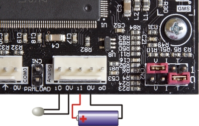
The HMI430/700 has two analog inputs. They can each be set to measure voltage, with 0-10V range and a 0-3.3V range, 0-20mA current and temperature using an external NTC thermistor.
Mode setting
The two red jumpers in the picture above set the analog input mode. The bottom one is for analog input 0, the top one is for analog input 1. Notice there are 3 positions labelled ‘V’, ‘I’ and ‘T’. The mode is determine by which pair of pins the jumper sits across.
| Jumper position | Mode |
|---|---|
| T | Thermistor temperature measurement mode |
| I | 0-20mA |
| V | 0-10V |
| No jumper | 0-3.3V |
In the picture above analog input 0 is set for temperature, and analog input 1 is set for 0-10V.
Connections
In both voltage and current modes, the pin labelled i0 or i1 must be positive with respect to the 0V pin. The picture above shows a battery connected to i1 so its voltage can be measured. Not the + polarity sign.
For current mode this means that a typical 2-wire 4-20mA transmitter will connect between the input pin (i0 or i1) and the positive supply voltage. The full scale voltage drop (“burden voltage”) in current mode is 3.3V
In thermistor mode and NTC thermistor simply connects between the input pin and 0V. The controller is optimised for thermistors with a resistance at 25°C of between 5K and 10K Ohm, but can be used with other resistances at reduced resolution.
More on temperature measurement
Thermistor temperature measurement is a great way to go for temperatures in the range -50°C up to 120°C or more. Dollar for dollar thermistors provide the best accuracy and require very little in the way of special electronics (compared to thermocouples or RTDs). They have one drawback: they are very non-linear, so you need to do some math to get from a raw reading to an actual temperature value. Fortunately, we have made it really easy for you with the thermistor hash command.
The fixed excitation resistor in the HMI430 thermistor circuit is 5765Ω. You will generally get the best results, i.e. resolution, if you pick a thermistor with around 5K – 10K resistance at the temperature you are mainly interested in.
Example: Measure in °C the thermistor connected on analog input i1. The thermistor data is:
- R25 5k Ohm (resistance at 25°C)
- Beta 3988
- Required measurement range 0 – 60°C (32 – 140°F)
In your program you would include the following line of code:
   fAnIn      1                                                           ;reads the analog value on i1
   #Thermistor Params(5000,3988) Feed(3.3,3.3,5765) RangeC(0,60) Order(5) ;convert to °C
Floating point register W now has the temperature in °C. To convert to °F:
   fLoadW    1.8      ;convert to °F by using F = 1.8 * C + 32
   fMul
   fLoadQ    32
   fAdd
The temperature in °F is now in floating point register W.
For more on thermistor temperature measurement see the full description of the #Thermistor command here.
Because the HMI430 has an awesome 12-bit analog resolution, you can also use the thermistor mode with a PT1000 (don’t try a PT100, though). Expect to get about 1°C resolution.
Measuring a potentiometer
You could also use “T” mode to measure a normal potentiometer. “T” provides 3.3V via 5765Ω, so if you have a 10kΩ pot, the maximum voltage you’ll get is:
   10000/(5765 + 10000) = 0.634
   0.634 * 3.3 = 2.09V
In fact, we don’t need the actual voltage, 0.634 is actually the maximum value you’ll get from fAnIn. So for this example, fAnIn will return 0.0 thru 0.634 over the entire travel of the potentiometer.
4-20mA measurement
In ‘I’ mode the analog input range is 0-20mA. This means that for 4-20mA measurement you need to calculate out the 4mA offset. That’s quite simple with the HMI430’s floating point instructions. The advantage is that by going to 0mA you have the possibility of detecting a broken input wire.