PID characterization: Preparing your process.
In order to properly characterize your process you need to have it set up in a manner that allows you to run it open loop and get stable results out of it. I can explain this best by way of an actual example.
In order to prepare this course I needed a sample system to work on. I didn’t really want to be messing around with electric kettles, water and 240V. I also needed something portable, so I could take it home at the weekend and back to work on Monday. So we made up a “contraption”. It consists of a length of aluminium angle about 150mm long, with a 5W resistor fastened to it one end and and a thermistor the other end. The resistor is 56 Ohms, so with 24V across it it will generate 10W of heat (that’s OK, because it’s heatsinked (heatsunk?) to the angle. At 24V the current is about 400mA, so an MMi200 can drive it directly. On the other end of the angle we attached the thermistor. I did it like that to introduce a nice juicy delay from one end to the other (not that I expect this to be a true fixed delay (dead time), but it will certainly ensure multiple time constants). The contraption is pictured here. You can see the heater/resistor on the left and the thermistor to the right. The object at the bottom of the picture, included to provide a scale, is called a slide rule and performs computations without batteries or software.
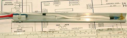
The thermistor is fed into the MMi200 in thermistor mode. We have thermistor temperature measurement down to a fine art, so that makes it easy.
As it happened I forgot to take home the intended 24V power supply on the Friday, so I had to make to with a 12V unregulated plugpack (“wall cube”) I had at home. That meant significantly less temperature rise (25% as much power). What I did was to place it inside a cardboard mailing tube and fill it up with polystyrene beanbag beads. For my purposes it didn’t matter that this gave me a different system. You can’t arbitrarily change your target system like that. You have to work with the actual system, and the right system, which will presumably be a prototype of some production item you intend to control with a SPLat.
Some of this is good and some is bad. The good thing was that by insulating my contraption, I was also insulating it to a large degree from environmental influences like drafts and from inadvertently being moved around on a cooler desk. Having a test setup that is stable and free of uncontrolled influences is important. The bad thing is that my 12VDC plug pack is unregulated, so right there I have an uncontrolled environmental influence. As it turned out the main run took place overnight, so the mains voltage would have been stable. The picture shows the complete unit in its red and white postal tube on my desk, and an MMi200 running the interactive PID program.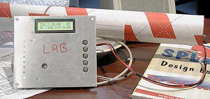
Only you can know your target system or process. Think about your experimental setup carefully, and arrange it to be free of external, uncontrolled and possible unmeasurable influences. At this stage you are interested in the behaviour of your system under ideal external conditions. You are going to be testing it open loop, remember, not under closed loop control. Also, make sure that the setup you work with is truly representative of the real end-product. Make sure that every part of the equipment that may affect its behaviour is present. Don’t leave out the thermal insulation or the checkvalve, and don’t make do with that sample pump you don’t intend to use in your final product … use the real thing!
The corollary to all this is that once you have characterized your system and got the PID control working, any change in the process may upset it. So watch out for inadvertent or deliberate changes. Don’t let Manufacturing substitute cheaper insulation or a smaller pump without your knowledge. Consider scenarios that may lead to changes in the field, such as wear and contamination. How well your controller copes with such changes is called its “robustness”.